Power tool

a technology of power tools and power tools, applied in the field of power tools, can solve the problems of unnecessarily labor-intensive and costly repair, replacement and/or inspection, and achieve the effect of inspected and/or repaired more quickly and more cost-effectively

Active Publication Date: 2019-05-21
MAKITA CORP
View PDF36 Cites 6 Cited by
  • Summary
  • Abstract
  • Description
  • Claims
  • Application Information

AI Technical Summary

Benefits of technology

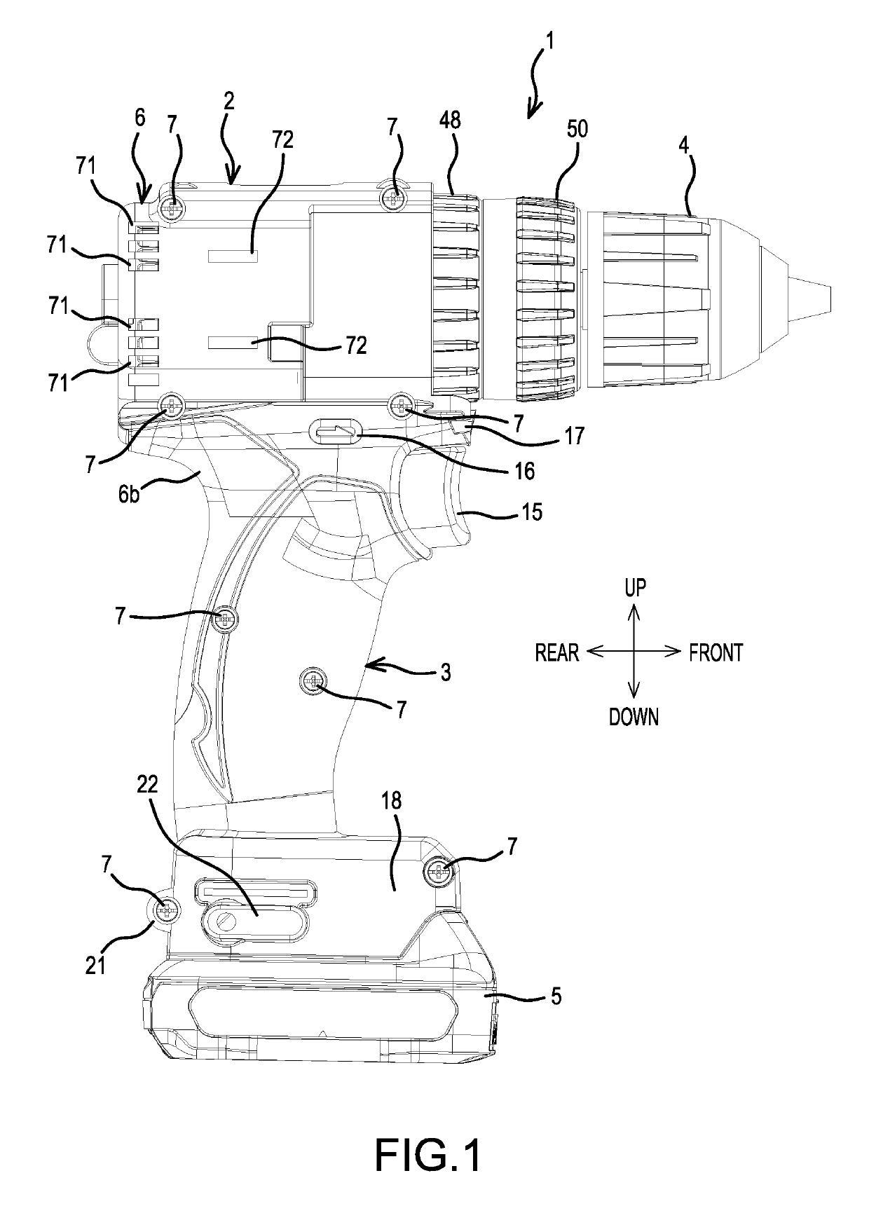
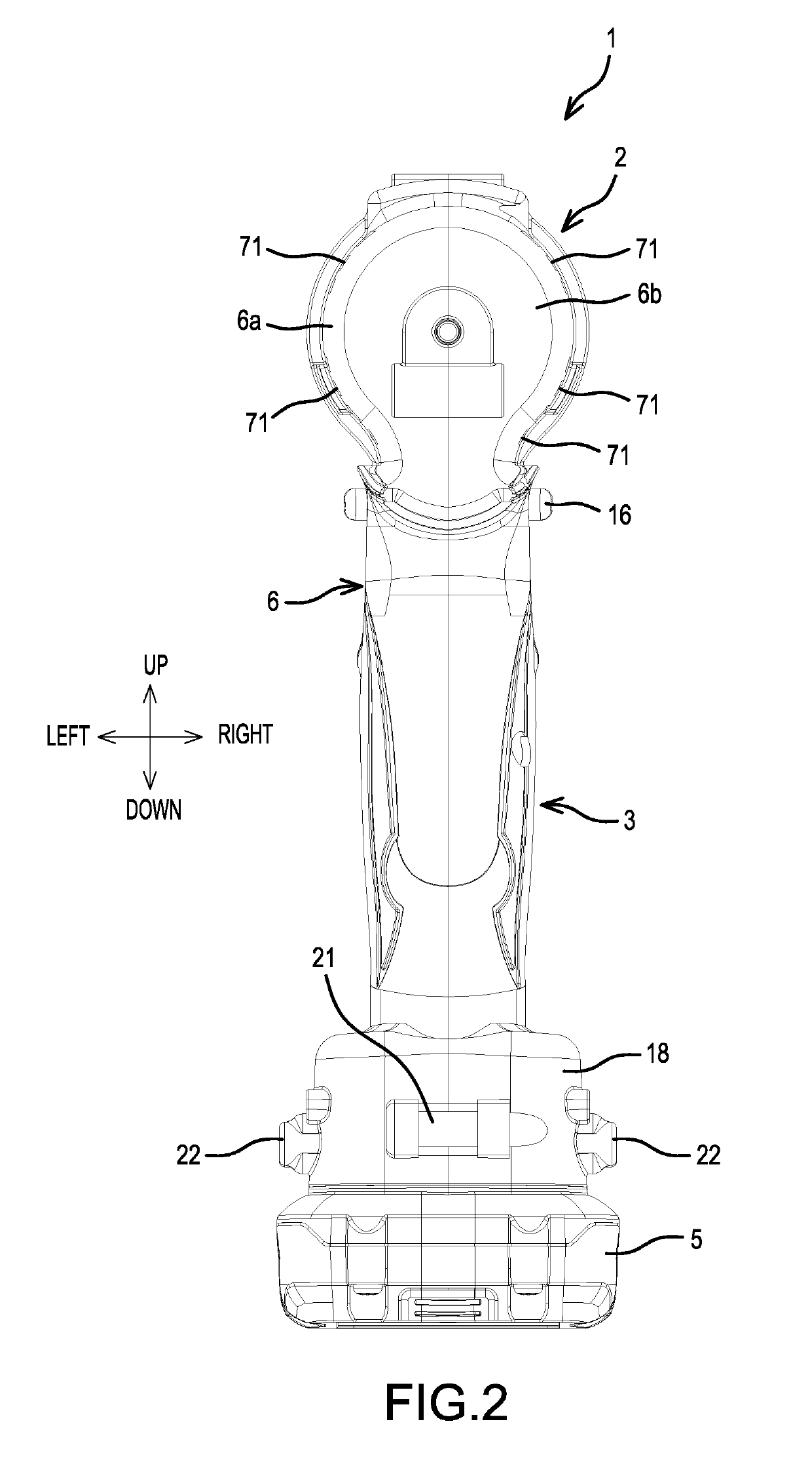
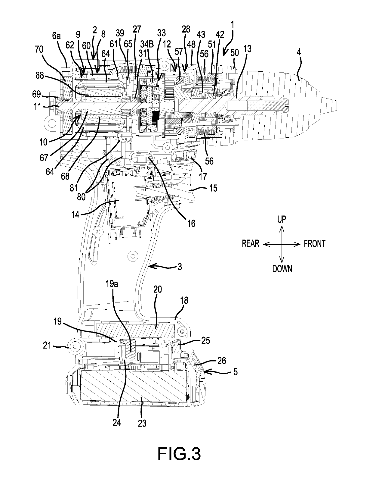
[0005]An aspect of the present disclosure is therefore to provide a power tool having a brushless motor that can be repaired and / or inspected more easily and efficiently.
[0014]The disclosed power tool having a brushless motor can be inspected and / or repaired more quickly and more cost-effectively than a conventional power tool having a brushless motor.

Problems solved by technology

This makes repair, replacement and / or inspection unnecessarily labor-intensive and costly.

Method used


Image

  • Power tool
  • Power tool
  • Power tool

Examples


embodiment 1

[0087]2. A power tool , wherein the first power-supply line is provided with a first connection terminal, the second power-supply line is provided with a second connection terminal and the first connection terminal is releasably connected to the second connection terminal.

[0088]3. A power tool according to embodiment 1 or 2, wherein second the power supply line is connected to the coil such that a sensor circuit board connected to the stator is removable from the stator without moving the power supply line.

[0089]4. A power tool, comprising a stator comprising a coil; a rotor configured to rotate with respect to the stator; a tool-accessory retaining part configured to be driven by the rotor; a fusing terminal fixed to the stator and connected to the coil; and a power-supply line that comprises stranded wires and is configured to supply electric current to the coil, wherein the power-supply line is connected to the fusing terminal and includes a stranded-wire-fray preventing means fo...

embodiment 4

[0090]5. A power tool , wherein the power-supply line comprises a covered part that covers the stranded wires; and wherein the stranded-wire-fray preventing means comprises a covering-remaining part, and the power-supply line includes an exposed part at which the stranded wires are exposed, wherein the exposed part is located between the covered part and the covering-remaining part.


PUM


Abstract

A power tool includes a stator having a coil, a sensor circuit board attached to the stator and on which a magnetic sensor is provided, the sensor circuit board having a first side facing the stator and a second side opposite the first side, a rotor configured to rotate with respect to the stator, a tool-accessory retaining part configured to be driven by the rotor and a power-supply line configured to supply electrical power to the coil. The power-supply line is connected to the coil without traversing the second side of the sensor circuit board.

Description

CROSS-REFERENCE[0001]The present application claims priority to Japanese patent application serial number 2015-127986 filed Jun. 25, 2015, the contents of which are incorporated fully herein by reference.TECHNICAL FIELD[0002]The present disclosure relates to a power tool such as a driver-drill.BACKGROUND ART[0003]A driver-drill that utilizes a brushless motor is known. The brushless motor of the driver-drill comprises a sensor circuit board, on which rotation-detection devices are mounted. The rotation detection devices are configured to detect the positions of permanent magnets provided on a rotor and to output rotation-detection signals. The brushless motor also includes a stator having a stator core on which multiple coils are sequentially wound in a delta configuration.SUMMARY OF THE INVENTION[0004]In the above-described driver-drill, signal lines are fastened to the sensor circuit board, and power-supply lines are welded in place; consequently, unless all the signal lines and p...

Claims


Application Information

Patent Timeline
Patent Type & Authority Patents(United States)
IPC IPC(8): H02K7/14H02K3/52H02K11/215H02K11/00H02K29/08
CPCH02K11/0094H02K11/215H02K3/522H02K29/08B25F5/00H02J7/00H02K29/00
Inventor NIWA, AKIRA
Owner MAKITA CORP
Why Eureka
Try Eureka