
Systems and methods for an electromagnetic actuator

a technology of electromagnetic actuators and actuators, applied in the field of electromagnetic actuators, can solve the problems of increasing costs, increasing costs, and requiring more space, and achieve the effects of reducing magnetic flux, less amp-turns, and less copper windings

Active Publication Date: 2019-06-11
HUSCO AUTOMOTIVE HLDG
View PDF46 Cites 2 Cited by
  • Summary
  • Abstract
  • Description
  • Claims
  • Application Information

AI Technical Summary

Benefits of technology

The use of a permanent magnet enables the electromagnetic actuator to achieve higher output force with less copper windings, reducing costs and size, while maintaining efficient actuation and minimizing magnetic saturation, thus addressing the limitations of air gap reduction in existing technologies.

Problems solved by technology

Increasing the area of the flux carrying components can lead to added cost due to additional material, and also require more space, which offsets a desirable outcome of making the electromagnetic actuator smaller.
Additionally, a reduction in air gaps can extremely tighten the tolerances and clearances, which, for manufacturing purposes, can prohibitively increase costs.
Furthermore, a reduction in the air gaps can lead to high side loading forces (i.e., forces substantially perpendicular to the desired direction of actuation) if the armature is not kept fully centered.

Method used


Image

  • Systems and methods for an electromagnetic actuator
  • Systems and methods for an electromagnetic actuator
  • Systems and methods for an electromagnetic actuator

Examples


Embodiment Construction

[0020]Before any embodiments of the invention are explained in detail, it is to be understood that the invention is not limited in its application to the details of construction and the arrangement of components set forth in the following description or illustrated in the following drawings. The invention is capable of other embodiments and of being practiced or of being carried out in various ways. Also, it is to be understood that the phraseology and terminology used herein is for the purpose of description and should not be regarded as limiting. The use of “including,”“comprising,” or “having” and variations thereof herein is meant to encompass the items listed thereafter and equivalents thereof as well as additional items. Unless specified or limited otherwise, the terms “mounted,”“connected,”“supported,” and “coupled” and variations thereof are used broadly and encompass both direct and indirect mountings, connections, supports, and couplings. Further, “connected” and “coupled”...


PUM

PropertyMeasurementUnit
volume ratio Rvaaaaaaaaaa

Abstract

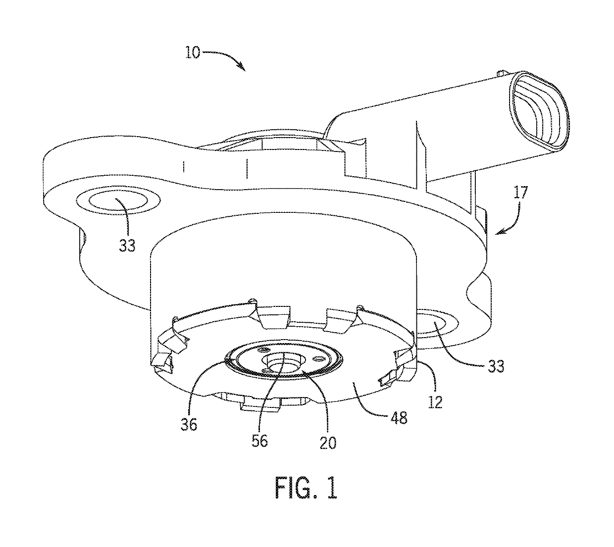
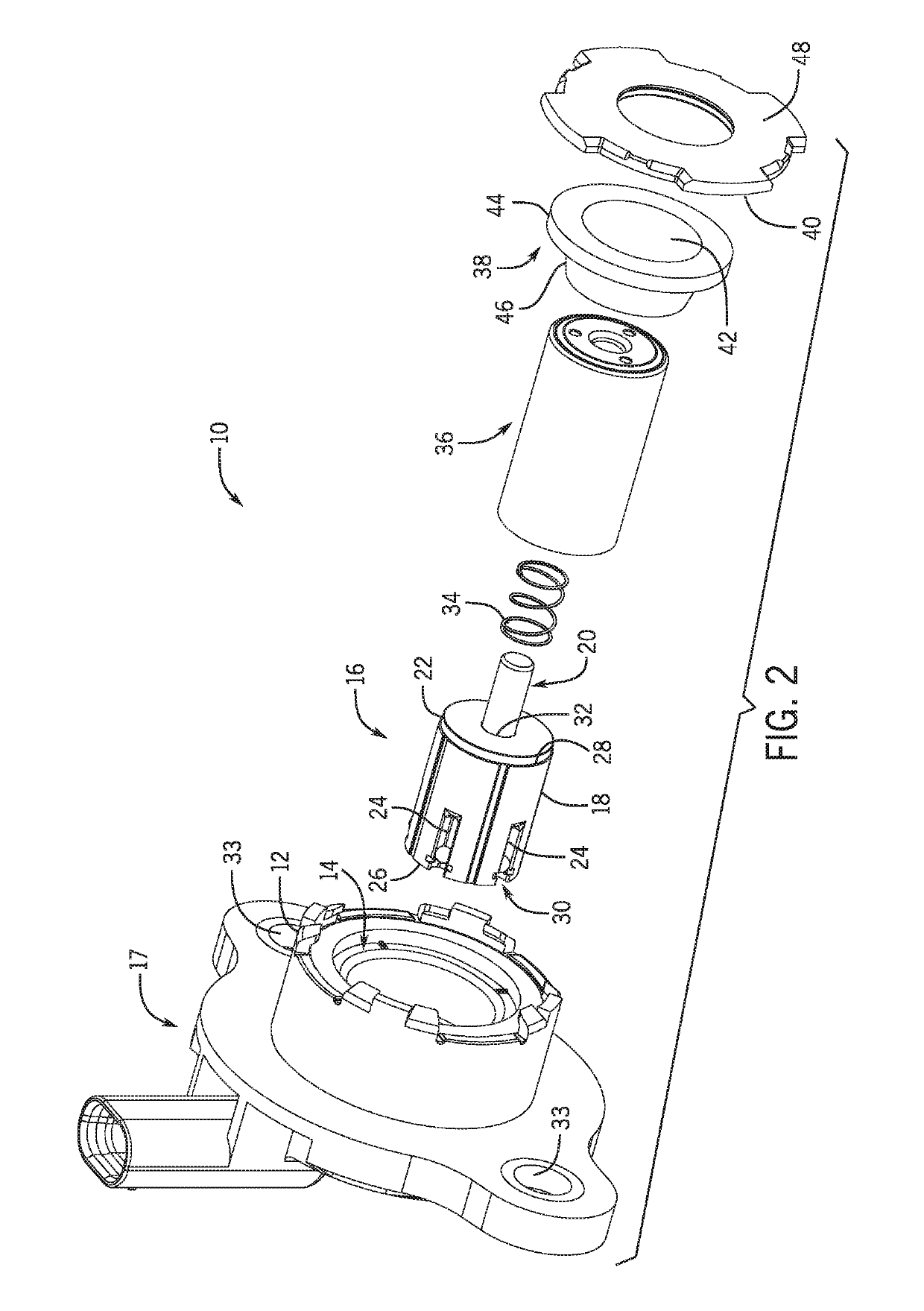
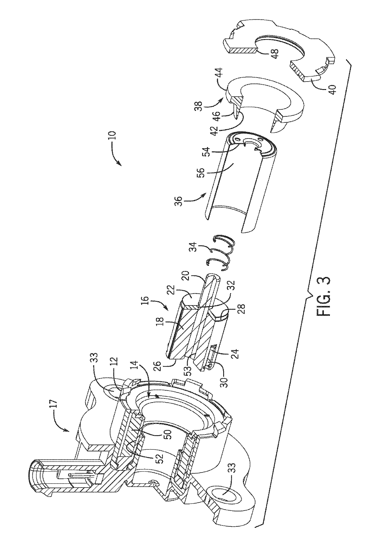
An electromagnetic actuator having a permanent magnet coupled to an armature of the electromagnetic actuator is provided. The electromagnetic actuator includes a housing, a pole piece arranged within the housing and secured by an end plate, and an armature assembly having an armature and a permanent magnet coupled to the armature. The armature is movable between a first position and a second position. The electromagnetic actuator further includes a wire coil positioned around the armature assembly and arranged within the housing. An actuation position of the armature between the first position and the second position is proportional to a magnitude of current applied to the wire coil.

Description

CROSS-REFERENCES TO RELATED APPLICATIONS[0001]The present application is based on, claims priority to, and incorporates herein by reference in its entirety, U.S. Provisional Patent Application No. 62 / 309,505, filed Mar. 17, 2016, and entitled “Systems and Methods for an Electromagnetic Actuator.”STATEMENT REGARDING FEDERALLY SPONSORED RESEARCH[0002]Not Applicable.BACKGROUND[0003]The present disclosure relates generally to electromagnetic actuators and, more specifically, to a variable force solenoid having a permanent magnet.[0004]Electromagnetic actuators (e.g., a variable force solenoid) typically include a wire coil positioned within a housing and around a moveable armature. A current can be applied to the wire coil to produce a magnetic field which can then actuate (i.e., move) the moveable armature with respect to the housing. Current trends are leading towards improving the output force and efficiency of electromagnetic actuators; however, this requires decreasing magnetic los...

Claims


Application Information

Patent Timeline
Patent Type & Authority Patents(United States)
IPC IPC(8): H01F7/00H01H47/22H01F7/16H01H45/04H01H51/06H01F7/08
CPCH01H51/06H01F7/1615H01H45/04H01H47/22H01H2235/01H01F2007/086H01F2007/163H01F7/081
Inventor WARDLE, DEANFRICKE, MICHAEL
Owner HUSCO AUTOMOTIVE HLDG
Learn More