Narrow belt conveyor with 90 degree cross transfer

a belt conveyor and cross-transfer technology, applied in the direction of conveyor parts, roller-ways, transportation and packaging, etc., can solve problems such as significant friction

Active Publication Date: 2019-07-16
SKARLUPKA MFG
View PDF22 Cites 11 Cited by
  • Summary
  • Abstract
  • Description
  • Claims
  • Application Information

AI Technical Summary

Benefits of technology

[0010]It is an object of the present invention to provide an effective and readily maintainable conveyor.
[0012]It is another object of the present invention to provide a narrow belt conveyor in which the motion and disposition of the belts is well regulated and suited to conveying parcels.
[0013]It is a further object of the present invention to provide a narrow belt conveyor which can operate without any pneumatic components.

Problems solved by technology

These belts can securely support the weight of parcels because they are entirely supported beneath, however, there is significant friction as the belts slide on the supporting surface.

Method used


Image

  • Narrow belt conveyor with 90 degree cross transfer
  • Narrow belt conveyor with 90 degree cross transfer
  • Narrow belt conveyor with 90 degree cross transfer

Examples


Embodiment Construction

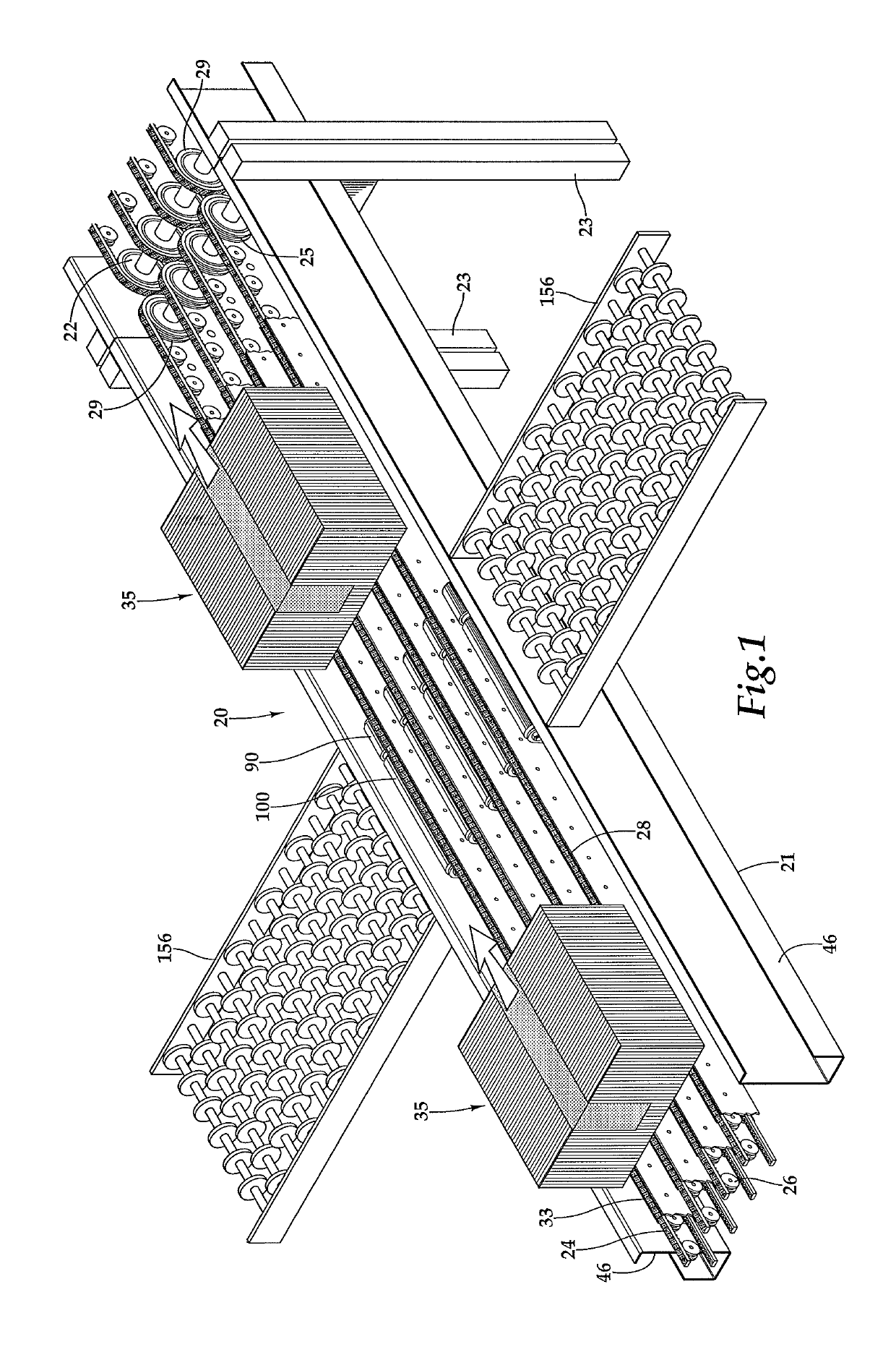
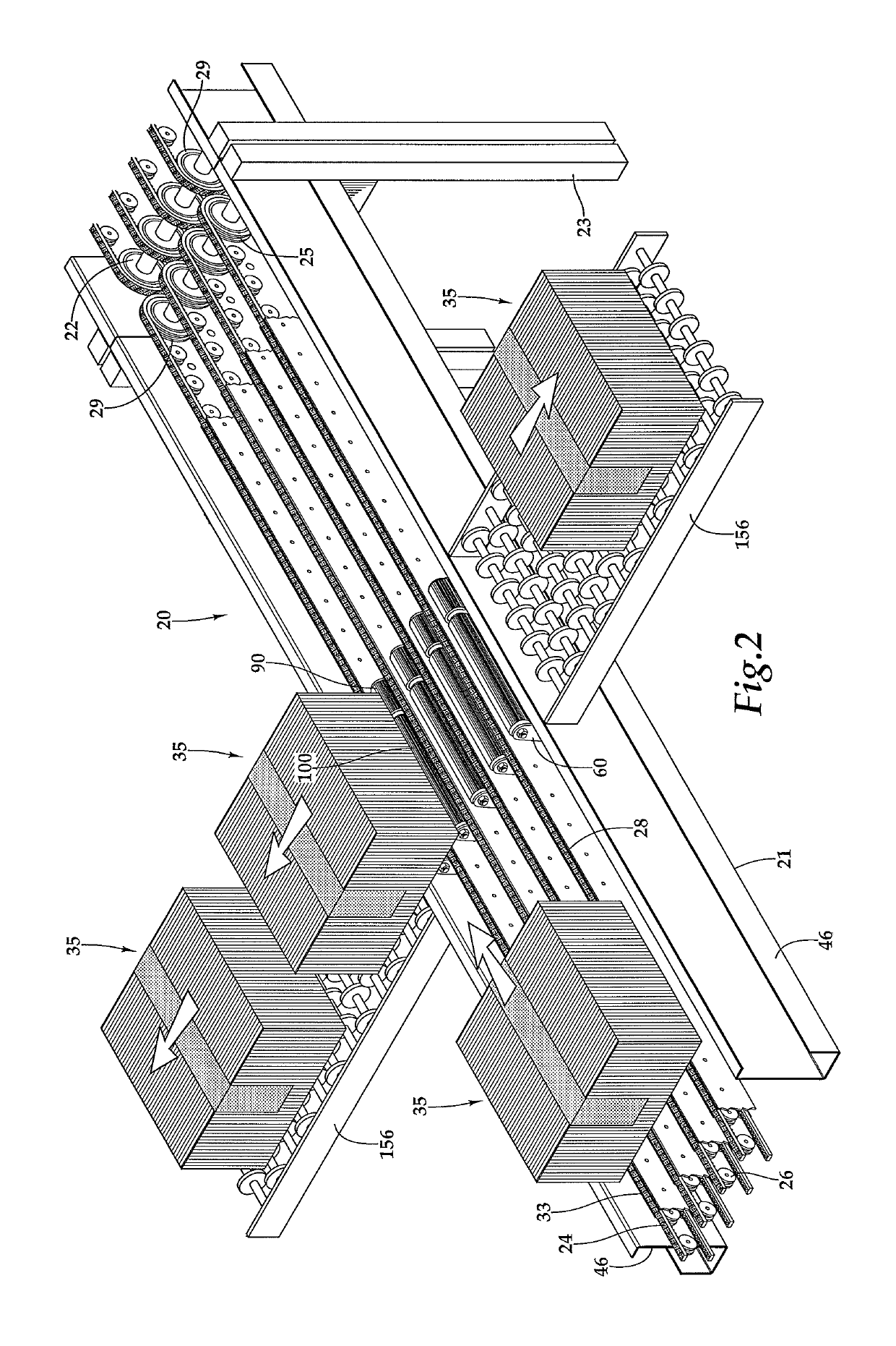
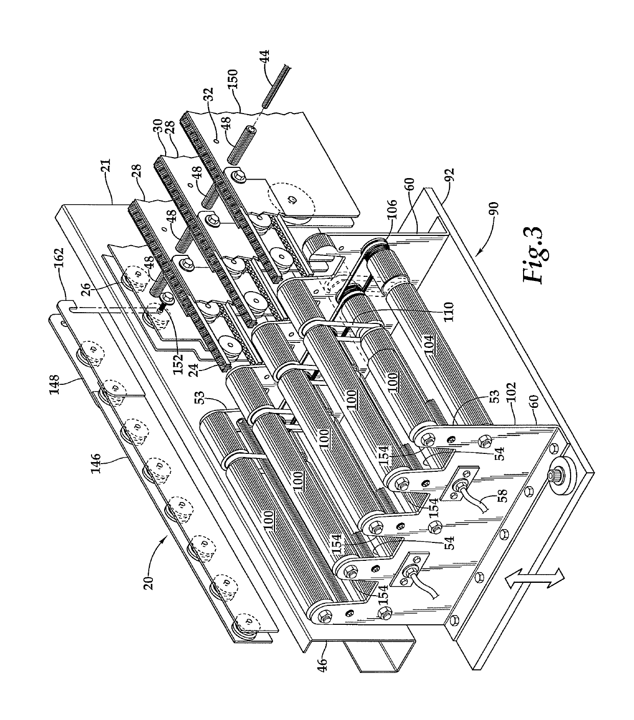
[0023]Referring more particularly to FIGS. 1-7, wherein like numbers refer to similar parts, a modular conveyor 20 is shown in FIG. 6. The conveyor 20 is about nine feet long and has a frame 21 with bent metal side members 46 as shown in FIG. 1. The frame 21 may include legs 23 to position the conveyor at a desired elevation. A plurality of conveyors 20 may be positioned end to end and their respective frames 21 secured together with connector plates 56 having six square holes to receive bolts therein.

[0024]The conveyor 20 has an inlet motorized roller 22 and an outlet motorized roller 25 which are mounted to the side members 46 of the frame 21. Both rollers 22, 25 are for example, 1.9 inch diameter 24 V DC motors such that they may function as drive rollers. Typically both rollers will drive at the same time and may be provided with a controller, not shown, which allows the drives to work together by synching the motors in open loop. It should be noted that the conveyor 20 is symme...


PUM


Abstract

A conveyor has looped conveying belts extending between grooved inlet and outlet rollers mounted to a frame, these rollers driven by motorized drive rollers. Each belt has an outwardly facing surface which engages a conveyed article, and an inwardly extending protrusion which engages the grooves of rollers rotatably mounted between parallel plates. The plates extend downwardly to be fixed to cross members which extend between the sides of the frame. A subframe supports upper rolls which are driven by belts connected to lower rolls, including motorized drive rolls. The subframe is mounted to an elevator platform to move the upper rolls between a retracted position and an extended position in which the upper rolls extend beyond the conveying belts which pass through gaps between the upper rolls, such that a conveyed article is moved by the upper rolls in a direction perpendicular to the direction of the conveying belts.

Description

CROSS REFERENCES TO RELATED APPLICATIONS[0001]This application is a continuation of U.S. application Ser. No. 16 / 052,305 filed Aug. 1, 2018, which claims priority on U.S. App. No. 62 / 564,723 filed on Sep. 28, 2017, the disclosure of both of which applications are incorporated by reference herein.STATEMENT AS TO RIGHTS TO INVENTIONS MADE UNDER FEDERALLY SPONSORED RESEARCH AND DEVELOPMENT[0002]Not applicable.BACKGROUND OF THE INVENTION[0003]The present invention relates to belt conveyors, and more particularly to such conveyors which may shift parcels ninety degrees to the direction of travel of the belts. In my U.S. Pat. No. 9,365,361, the disclosure of which is incorporated by reference herein, I showed a right-angle conveyor in which a small multibelt conveyor could be raised up between a series of rollers, to intermittently direct parcels 90 degrees to the direction of motion of the rollers.[0004]Known belt conveyors have a plurality of flexible looped belts which have end drive r...

Claims


Application Information

Patent Timeline
Patent Type & Authority Patents(United States)
IPC IPC(8): B65G13/02B65G47/64B65G47/54B65G15/12
CPCB65G47/54B65G47/643B65G15/12B65G13/02B65G2201/0285B65G13/12B65G23/44
Inventor SKARLUPKA, DONALD BRUCE
Owner SKARLUPKA MFG
Why Eureka
Try Eureka