Switching power supply

a power supply and power supply technology, applied in the field of switching power supplies, can solve the problems of power on resetting of an ic, malfunction of the under-voltage locking out function, etc., and achieve the effect of stable startup readily and effectively

Active Publication Date: 2016-03-22
FUJI ELECTRIC CO LTD
View PDF7 Cites 3 Cited by
  • Summary
  • Abstract
  • Description
  • Claims
  • Application Information

AI Technical Summary

Benefits of technology

[0016]Embodiments of the invention provide a switching power supply that improves rise up performance of the output voltage at the startup period and preventing an IC in the subsequent stage connected to the secondary side output terminal from undergoing power ON resetting and avoiding erroneous functioning of an under-voltage locking out function.
[0024]In some embodiments, because the output voltage monotonically rises up in the startup period, the switching power supply of the invention starts up stably without inviting troubles such as power-on resetting of an IC in the next stage connected to the secondary side output terminal, or malfunctioning of under-voltage locking out function. In addition, the construction of the invention only pulls down the CS signal to the ground potential and pulls up the FB signal to a voltage indicating an overload state in the startup period. Therefore, the switching power supply performs stable startup readily and effectively.
[0025]In some embodiments, because the oscillation frequency of the oscillator is restricted to a frequency higher than the audible frequency band as mentioned previously, a problem of so-called audible noise does not occur when the output current is restricted by reducing the oscillation frequency, which is a switching frequency. Thus, the present invention provides great advantages in practical application.

Problems solved by technology

If the DC output voltage Vout does not exhibit a monotonic increase characteristic, it may cause power ON resetting of an IC in the subsequent stage connected to the secondary side output terminal, or malfunction of the under-voltage locking out function.

Method used


Image

  • Switching power supply
  • Switching power supply
  • Switching power supply

Examples


Embodiment Construction

[0035]The following describes in detail a switching power supply according to a embodiments of the invention with reference to accompanying drawings.

[0036]The switching power supply of some embodiments has a basic construction, for example, of the forward type switching power supply as shown in FIG. 5. A switching power supply main body 1 that mainly composes the switching power supply has a switching element Q, which can be a MOSFET, that conducts switching of an input voltage Vin through a primary winding Ta of a transformer T. The switching power supply main body 1 rectifies an AC voltage developing across a secondary winding Tb of a transformer T with diodes DS2 and DS3, and makes the rectified voltage smooth with a smoothing circuit composed of a reactor L and an output capacitor Cout to obtain a specified output voltage Vout.

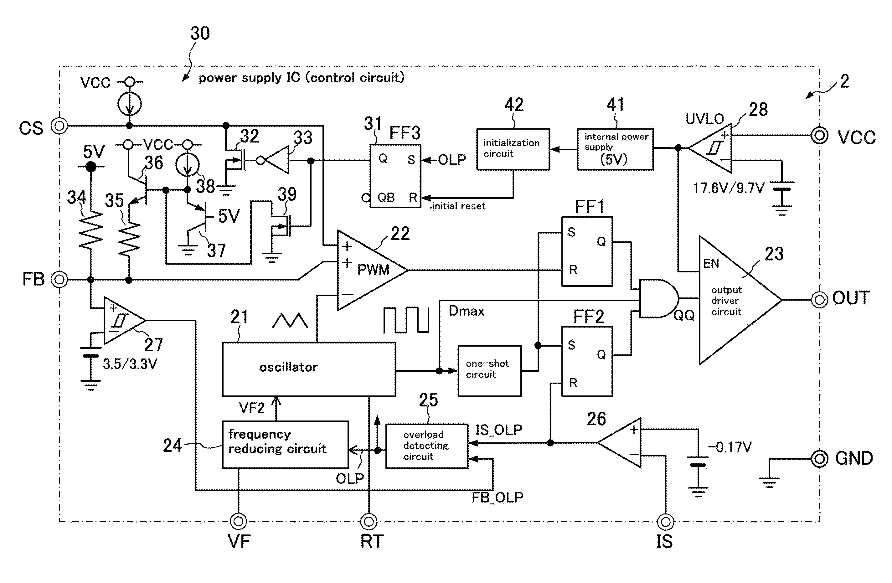
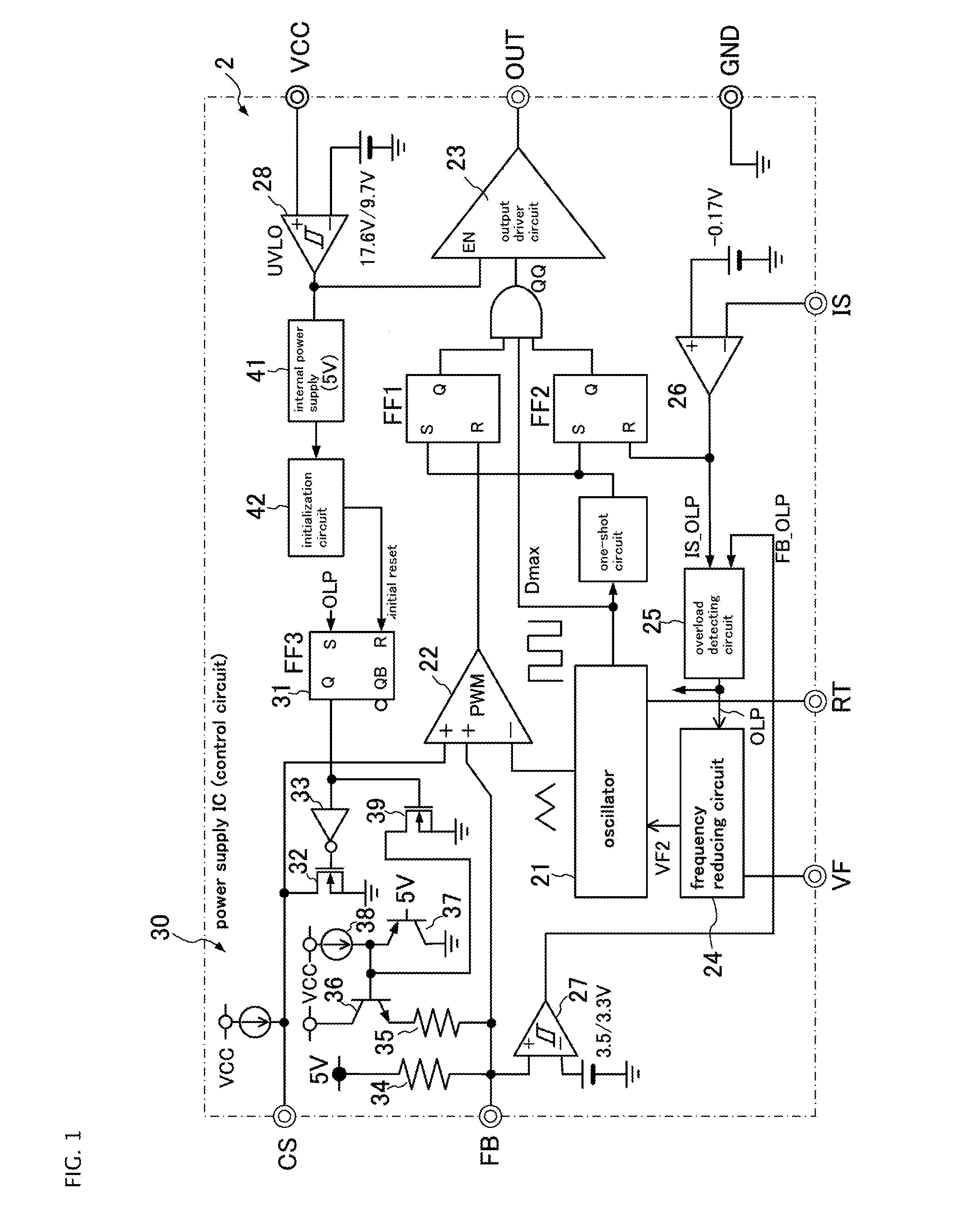
[0037]The switching power supply of this embodiment is characterized in that control circuit 2, which is a power supply IC 2, to control driving of the sw...


PUM


Abstract

In some aspects of the invention, a switching power supply can include a control circuit that conducts feedback control of a pulse width of a driving signal for switching the switching element according to an output voltage and settle the output voltage to a specified voltage level; a frequency reducing circuit that is disposed in the control circuit and reduces a frequency of the driving signal for switching the switching element upon detection of an overload state and limits an output current; and an initial state setting circuit that sets the control circuit to an overload detecting state for a predetermined period of time in a startup period of the control circuit. The initial state setting circuit can pull down a control voltage for a soft start signal for soft starting to the ground potential to inhibit generation of the driving signal and pulls up a feedback voltage signal.

Description

CROSS-REFERENCE TO RELATED APPLICATION[0001]This application is based on, and claims priority to, Japanese Patent Application No. 2012-286940, filed on Dec. 28, 2012, the contents of which are incorporated herein by reference.BACKGROUND OF THE INVENTION[0002]1. Field of the Invention[0003]Embodiments of the invention relate to switching power supplies in which rising up performance of an output voltage is improved at a startup period of the power supplies.[0004]2. Description of the Related Art[0005]FIG. 5 shows a schematic construction of a conventionally common switching power supply of a forward type. The switching power supply receives an input voltage Vin that is obtained by full-wave rectification of an AC voltage Vac with a diode bridge circuit DS1 and following smoothing with an input capacitor Cin. The switching power supply is mainly composed of a switching power supply main body 1 provided with a switching element Q that switches the input voltage Vin through a primary wi...

Claims


Application Information

Patent Timeline
Patent Type & Authority Patents(United States)
IPC IPC(8): H02M3/335H02M1/36H02M1/32
CPCH02M1/36H02M1/32H02M3/33553
Inventor MARUYAMA, HIROSHI
Owner FUJI ELECTRIC CO LTD
Why Eureka
Try Eureka