Sensing apparatus for blown fuse of rectifying wheel and associated methods

a technology of sensing apparatus and rectifying wheel, which is applied in the direction of fuses testing, associations for rectifying, instruments, etc., can solve the problems of diodes or fuses failing, requiring careful visual inspection, and rectifier still being operated, so as to achieve the effect of quick and effective sensing

Inactive Publication Date: 2005-04-28
SIEMENS ENERGY INC
View PDF18 Cites 11 Cited by
  • Summary
  • Abstract
  • Description
  • Claims
  • Application Information

AI Technical Summary

Benefits of technology

[0011] In view of the foregoing background, it is therefore an object of the present invention to provide a r

Problems solved by technology

When sufficient redundancy is provided in the form of multiple diodes and fuses for each phase, one or more diodes or fuses may fail and the rectifier can still be oper

Method used


Image

  • Sensing apparatus for blown fuse of rectifying wheel and associated methods
  • Sensing apparatus for blown fuse of rectifying wheel and associated methods
  • Sensing apparatus for blown fuse of rectifying wheel and associated methods

Examples


Embodiment Construction

[0023] The present invention will now be described more fully hereinafter with reference to the accompanying drawings in which preferred embodiments of the invention are shown. This invention may, however, be embodied in many different forms and should not be construed as limited to the illustrated embodiments set forth herein. Rather, these embodiments are provided so that this disclosure will be thorough and complete, and will fully convey the scope of the invention to those skilled in the art. Like numbers refer to like elements throughout and prime notation is used to indicate similar elements in alternate embodiments.

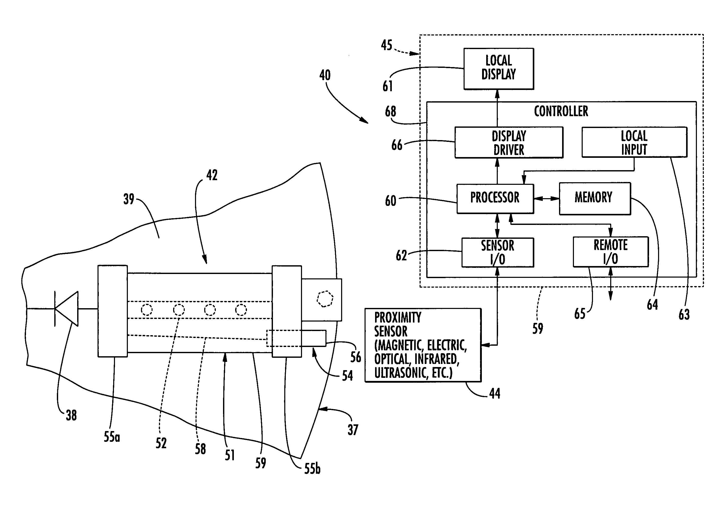
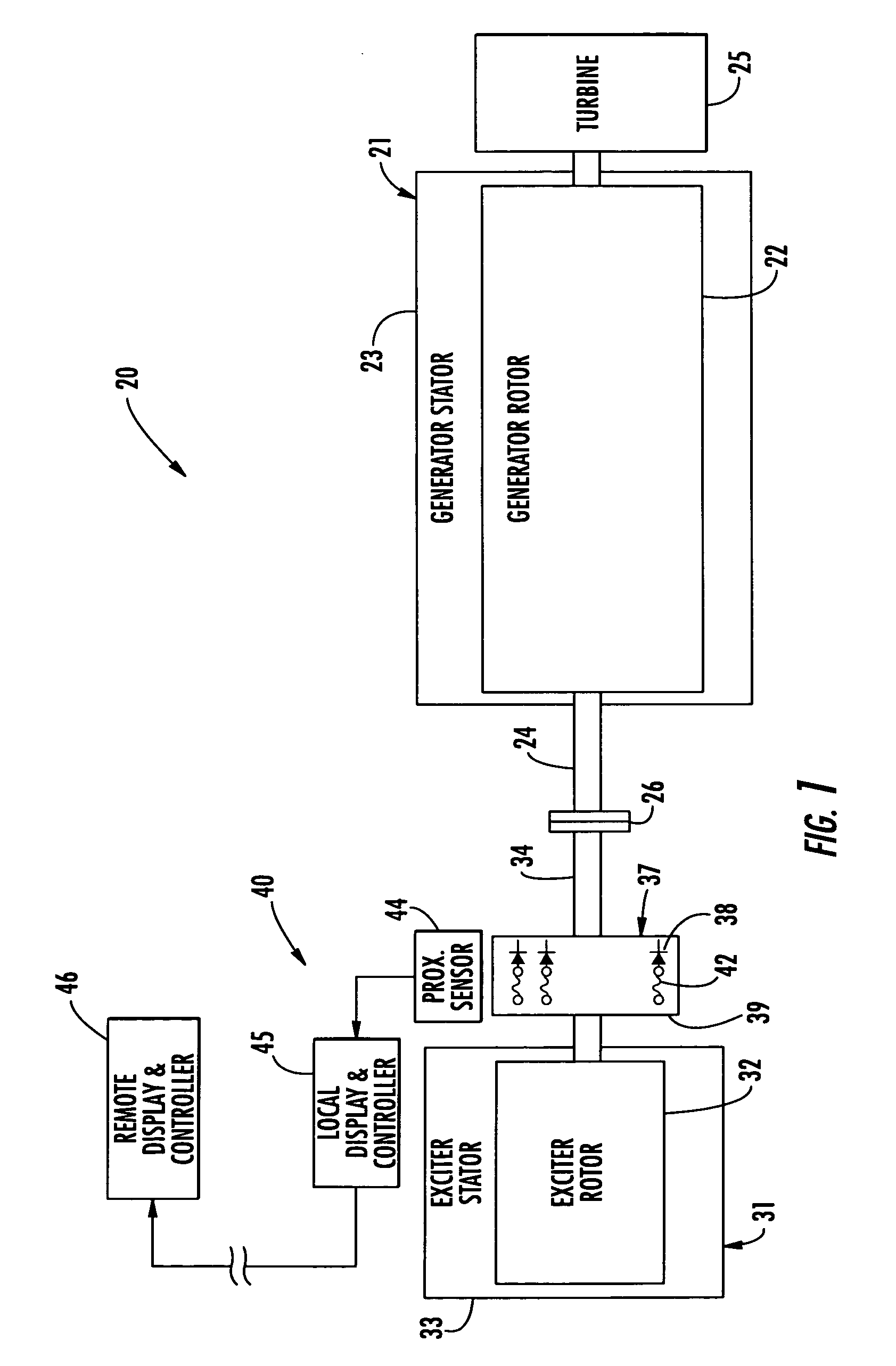
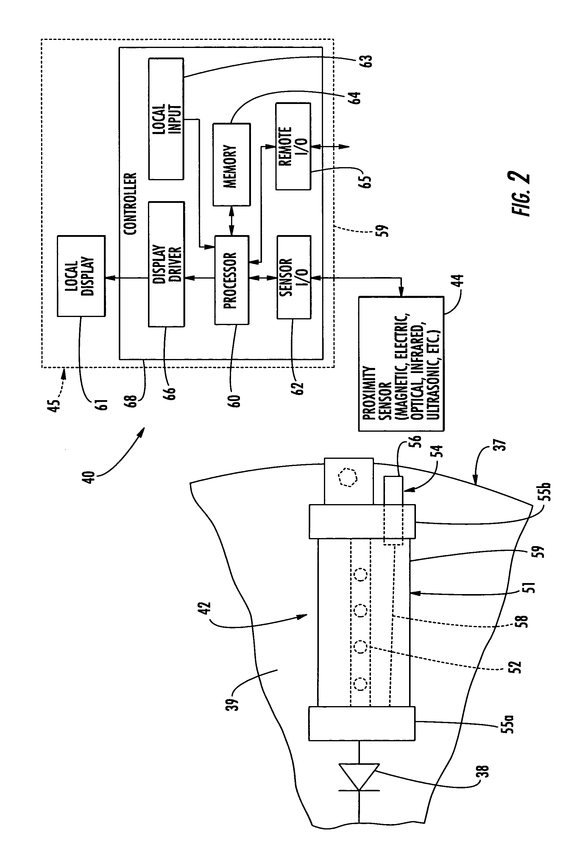
[0024] Referring initially to FIG. 1, the electrical apparatus 20 including the blown fuse sensing apparatus 40 in accordance with the invention is now described. The electrical apparatus 20 illustratively includes a generator 21 and an exciter 31 connected thereto. More particularly, the generator 21 includes a generator rotor 22 and generator stator 23 surroundi...


PUM


Abstract

A blown fuse proximity sensing device 40 is for use with a rectifying wheel 37 of a type including rectifying diodes 38 and associated fuses 42. Each fuse 42 may include a housing 51, a fuse element 52 carried by the housing, and a pop-out indicator 54 movable between a normal position and a popped-out position. In the popped-out position, the indicator 54 extends outwardly from the housing responsive to failure of the fuse element. At least one stationary proximity sensor 44 is mounted adjacent the rectifying wheel 37 for sensing positions of the pop-out indicators 54 without contact therewith during rotation of the rectifying wheel to thereby sense at least one blown fuse. The sensing device 40 may also include a local display 61, and a controller 68 connected to the stationary proximity sensor 44 for generating an indication of a blown fuse on the local display. The controller 68 may also generate at least one remote output, such as to be monitored by other plant control equipment.

Description

FIELD OF THE INVENTION [0001] The present invention relates to electrical power generation, and, more particularly, to detecting conditions of a rectifying wheel for a power generator and related methods. BACKGROUND OF THE INVENTION [0002] A typical power generator includes a shaft and a rotor carried by the shaft. Surrounding the generator rotor is a generator stator. A turbine, such as a gas combustion turbine, a water-driven turbine, or steam-driven turbine rotates the shaft. The generator rotor is supplied DC power typically from an exciter also driven by the shaft. As the generator rotor is turned within the generator stator, electrical power is produced and is delivered to the utility power grid. [0003] The exciter typically includes an exciter rotor carried by a shaft connected to the generator shaft. An exciter stator surrounds exciter rotor. Regulated DC power is supplied to the exciter stator so that AC power is produced by the exciter rotor as the exciter rotor is rotated...

Claims


Application Information

Patent Timeline
IPC IPC(8): G01R31/74H01H85/30H02K11/00H02K11/04
CPCG01R31/07H02K11/042H02K11/0047H01H85/306G01R31/74H02K11/25
Inventor LAU, JAMES F.BANTHIA, ANAND
Owner SIEMENS ENERGY INC
Why Eureka
Try Eureka