Supercharge Your Innovation With Domain-Expert AI Agents!

Enclosure mounting assembly

a technology for mounting assemblies and enclosures, which is applied in the direction of casings/cabinets/drawers, casings/cabinets/drawers details, electrical apparatus, etc., can solve the problems that conventional mounting assemblies do not permit secure mounting of assemblies, and conventional mounting assemblies cannot be used to mount different size enclosures required for different size electrical components

Active Publication Date: 2019-08-20
PHOENIX CONTACT DEVMENT & MFG
View PDF29 Cites 1 Cited by
  • Summary
  • Abstract
  • Description
  • Claims
  • Application Information

AI Technical Summary

Benefits of technology

Enables secure mounting of various-sized electrical enclosures on different-sized poles and flat support walls using a single assembly, reducing the need for multiple support structures and fastener hardware, enhancing versatility and ease of installation.

Problems solved by technology

Conventional mounting assemblies do not permit secure mounting of the assembly with supported electrical components on different sized poles or on flat support surfaces.
Additionally, conventional mounting assemblies cannot be used to mount different size enclosures required for different size electrical components.
Compounding enclosure size issues, an enclosure may have to be mounted on different diameter poles.
These problems require a stock of different support structures adapted for use with different enclosures with may be secured on walls or on poles.

Method used


Image

  • Enclosure mounting assembly
  • Enclosure mounting assembly
  • Enclosure mounting assembly

Examples


Embodiment Construction

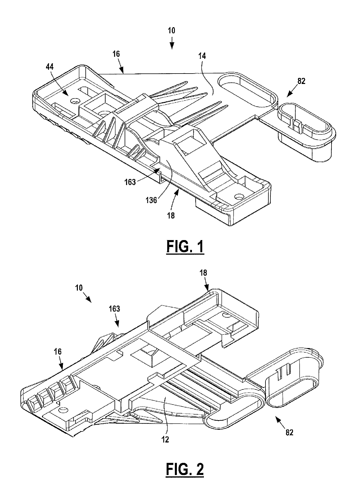
[0039]FIGS. 1 and 2 show an enclosure mounting assembly 10 having two member bodies 16 and 18. Assembly 10 has a generally flat shape with an enclosure face 12 and an opposed support mounting face 14. Body 16 is illustrated in FIGS. 3-9. Body 18 is illustrated in FIGS. 10-13. Bodies 16 and 18 may be molded from conventional plastic resin.

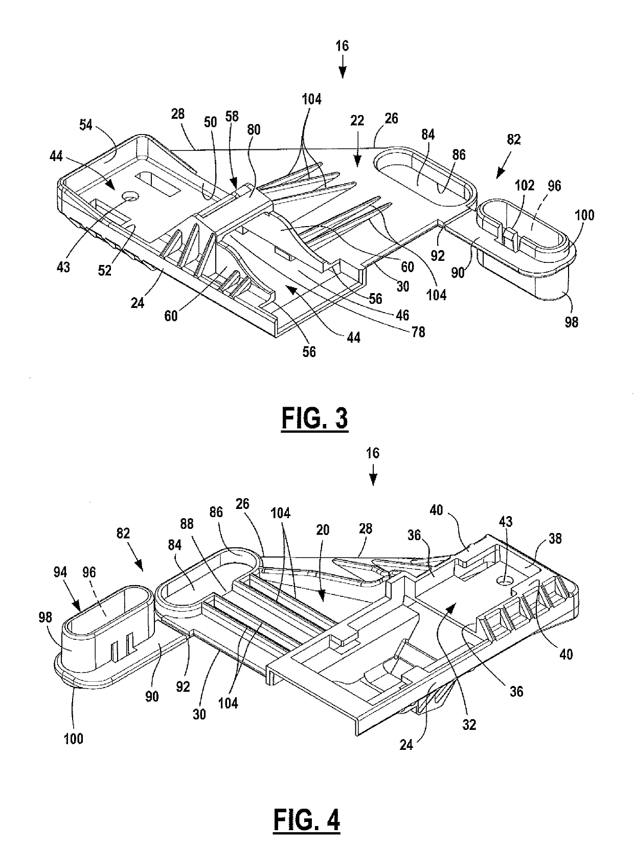
[0040]As shown in FIGS. 3-4, first member body 16 is generally flat, having opposed enclosure and support mounting faces 20, 22. First body 16 extends from body bottom 24 to body top 26 and from body outer side 28 to body inner side 30. While faces 20, 22 are shown in the figures as having the shape of an irregular pentagon, other shapes are possible.

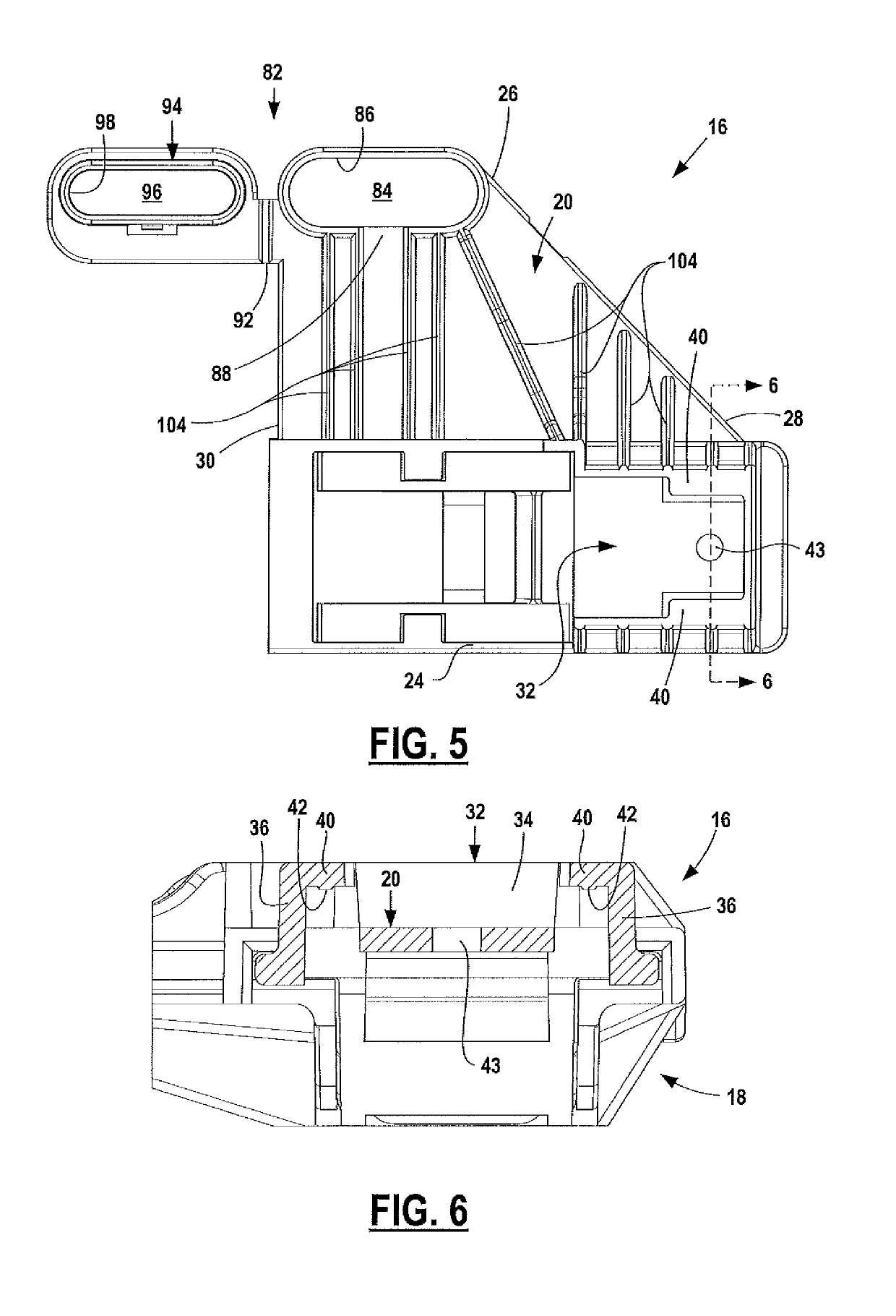
[0041]First body 16 enclosure face 20 has an enclosure engagement element 32 proximate body bottom 24 and body outer side 28. Engagement element 32 has a slot recess 34 generally defined by walls 36, 38 extending away from face 20 and lips 40 overlying face 20. Each lip 40 includes a rib 42 extending fr...


PUM


Abstract

An enclosure mounting assembly for mounting different sized enclosures onto support poles or flat support walls.

Description

FIELD OF THE DISCLOSURE[0001]The disclosure relates to assemblies for mounting electrical component enclosures on supports. In particular, the disclosure relates to assemblies for securing different types of electrical component enclosures on support poles of different diameters or on flat support walls.BACKGROUND OF THE DISCLOSURE[0002]Electrical components, typically circuit boards with printed circuits and electronic components on the boards are installed in environmentally and electrically protective enclosures. It is well-known to mount these enclosures in exposed locations on poles or on flat support walls.[0003]Conventional mounting assemblies do not permit secure mounting of the assembly with supported electrical components on different sized poles or on flat support surfaces. Additionally, conventional mounting assemblies cannot be used to mount different size enclosures required for different size electrical components. Typically a specific mounting assembly is required fo...

Claims


Application Information

Patent Timeline
Patent Type & Authority Patents(United States)
IPC IPC(8): F16M13/02H05K5/02
CPCH05K5/0204F16M13/02
Inventor WALKER, KEVINPOTTEIGER, NATHAN
Owner PHOENIX CONTACT DEVMENT & MFG
Features
  • R&D
  • Intellectual Property
  • Life Sciences
  • Materials
  • Tech Scout
  • Unparalleled Data Quality
  • Higher Quality Content
  • 60% Fewer Hallucinations
Learn More