Nailer driver blade stop

a technology of nailer blade and driver, which is applied in the direction of nailing tools, manufacturing tools, etc., can solve the problems of providing an operator with a fastener driving mechanism, many available fastening tools do not adequately guard the moving parts of the nailer driving mechanism from damage, and failures are even more pronounced, so as to reduce or eliminate misfires

Active Publication Date: 2019-10-08
BLACK & DECKER INC
View PDF104 Cites 4 Cited by
  • Summary
  • Abstract
  • Description
  • Claims
  • Application Information

AI Technical Summary

Benefits of technology

[0006]The invention in its many and varied embodiments disclose herein solves the problems regarding control of a driver blade during its return phase after driving a nail into a workpiece. It reduces or eliminates misfires resulting from the recoil or undesired driver blade return dynamics of the driver blade after driving a fastener into a workpiece.
[0012]In an embodiment, at least a portion of a bumper and at least a portion of the driver blade can form a pivot angle upon their initial contact of the bumper and the driver blade. In an embodiment, the fastening tool can have a bumper adapted for impact by the driver blade during a portion of the return phase; a driver blade stop adapted for impact by the driver blade during a portion of the return phase; and a magnet which magnetically attracts at least a portion of the driver blade during a portion of the return phase. The value of the pivot angle can determine the rebound angle between the nailer profile axis and the nail channel centerline.
[0014]The method of controlling rebound in a fastening tool can also have the steps of: providing the bumper, wherein the bumper has at least an impact portion which is adapted to receive an impact from the driver blade; the bumper receiving an impact from the driver blade, such as reversibly impacting at least a portion of the driver blade into the bumper, such as into the impact portion; and configuring a driver blade axis to have an angle greater than zero with a nail driving axis as a result of said impacting during at least a portion of the return phase. In an embodiment, the method of controlling rebound in a fastening tool can further have the step of providing the bumper which has a surface configured to provide a pivot angle. In another embodiment, the method of controlling rebound in a fastening tool can also have the step of reversibly deforming the bumper by contact by the driver blade. In another embodiment, the method of controlling rebound in a fastening tool can further have the step of providing the driver blade, wherein the driver blade has a surface configured to provide a pivot angle.

Problems solved by technology

However, many fastening tools which are available do not provide an operator with fastener driving mechanisms which exhibit reliable fastener driving performance.
Many available fastening tools do not adequately guard the moving parts of a nailer driving mechanism from damage.
These failures are even more pronounced during high energy and / or high-speed driving.
Improper driving of fasteners, failure of parts and damage to the tool can occur.
Additionally, undesired driver blade recoil and / or undesired driver blade return dynamics can frequently occur and can result in misfires, jams, damage to the tool and loss of work efficiency.
This recoil energy in the driver blade can frequently cause an unintentional driving of a second fastener.
In the case of a cordless nailer having mechanical return springs, this unintentional driving of a second nail can be very common.
Unintentionally driving a second nail can risk damage to the work surface, jams, misfires, or tool failures.
Many available fastening tools experience misfire and produce unacceptable rates of damaged fasteners when fired.
Further, many available fastening tools do not adequately guard the moving parts of a nailer driving mechanism from damage.
In addition to the above, many available cordless nailer designs which do not use a piston cylinder arrangement are only capable of driving finish nails.
They are unable to drive fasteners into concrete and / or metal.
They are also inadequate to drive fasteners into various types of hard or dense construction materials.

Method used


Image

  • Nailer driver blade stop
  • Nailer driver blade stop
  • Nailer driver blade stop

Examples


Embodiment Construction

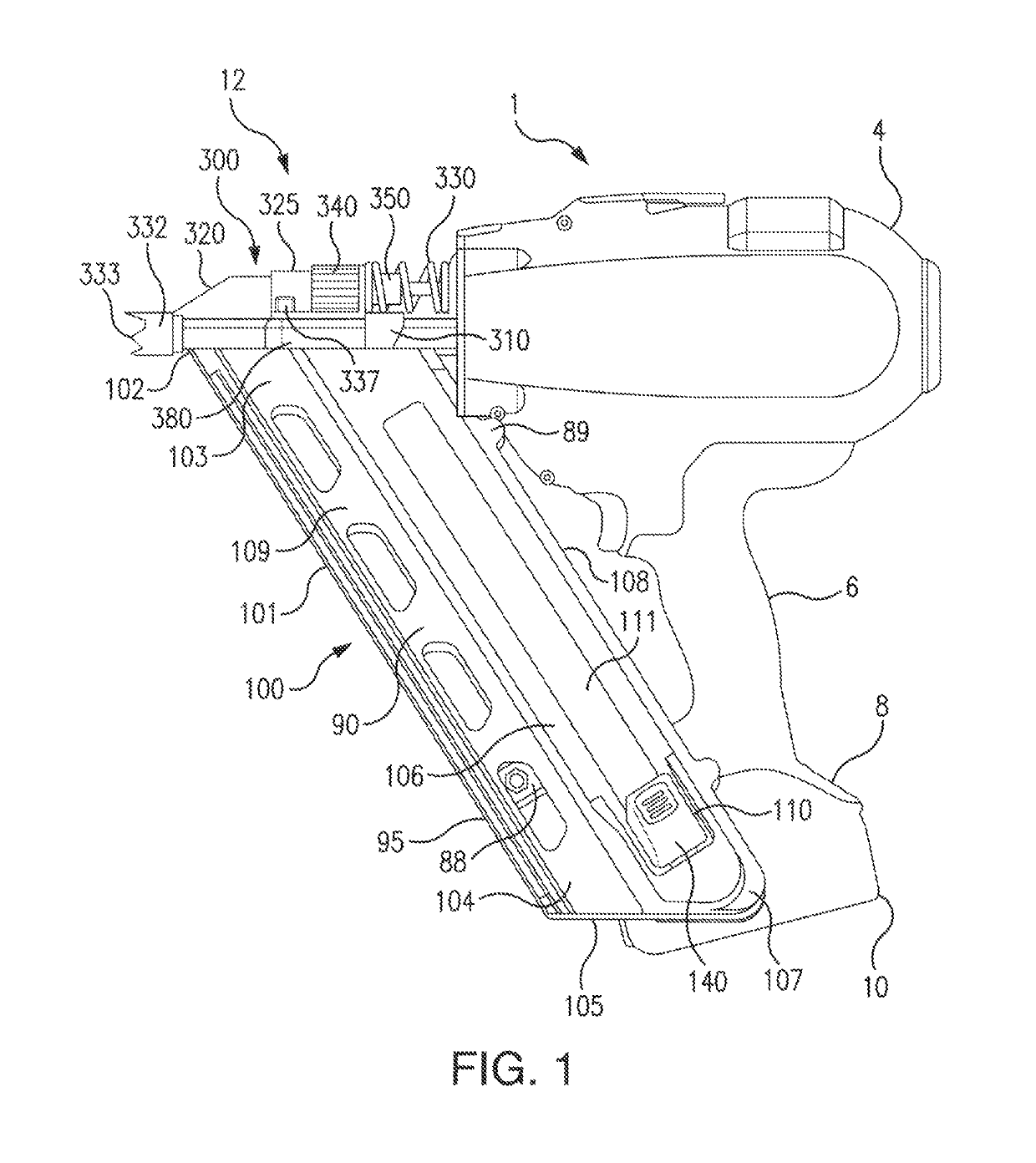
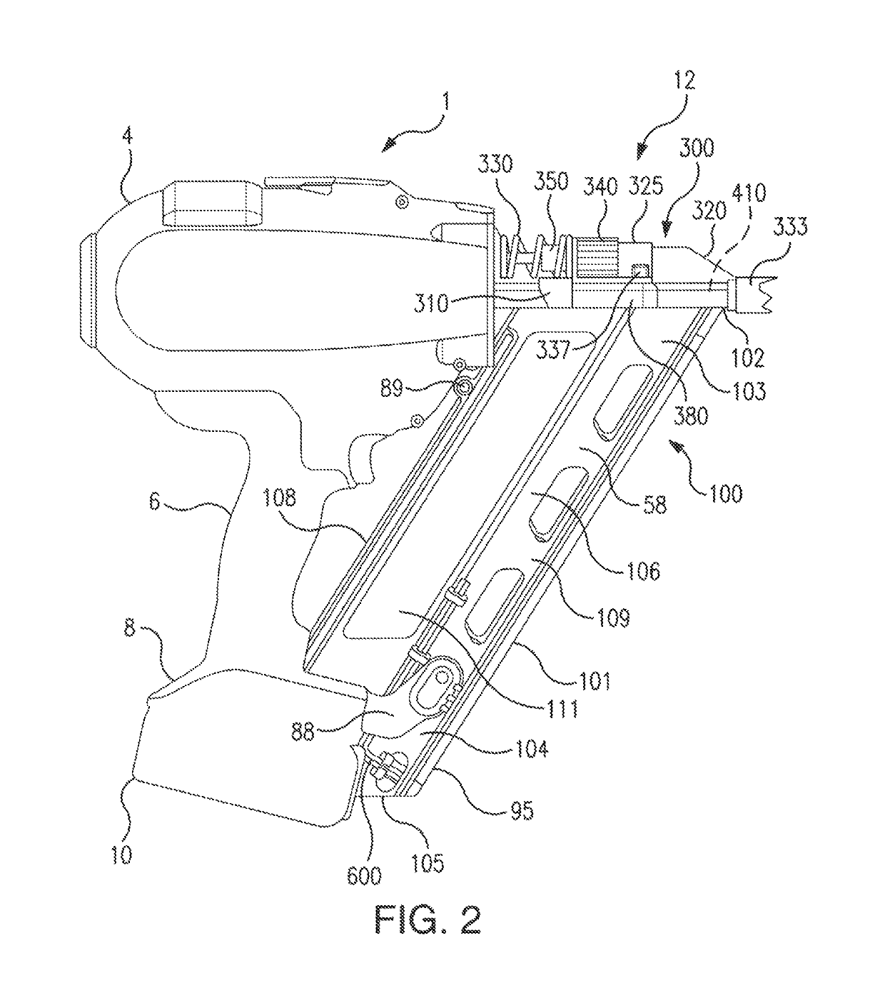
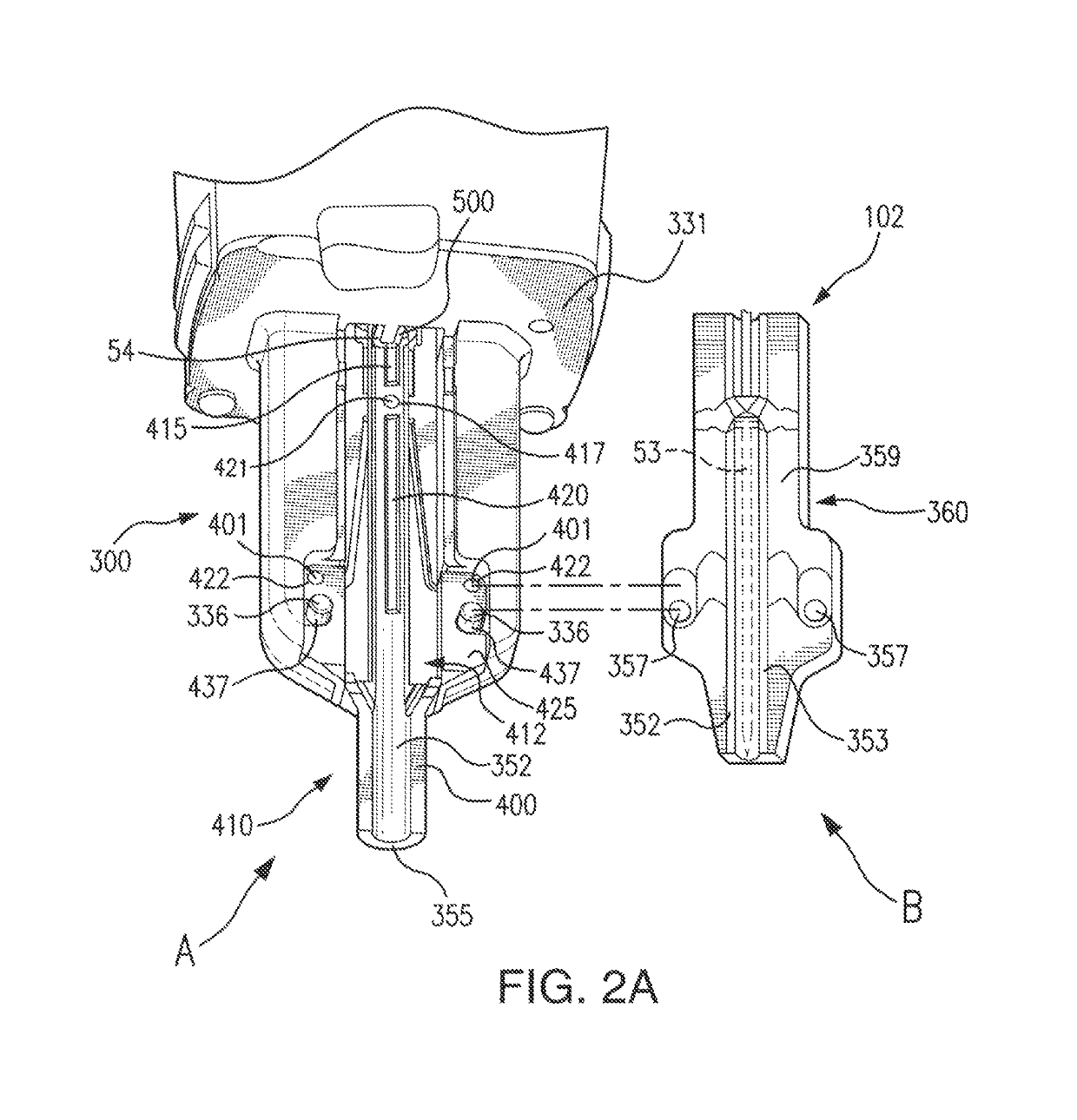
[0052]In a fastening tool such as a nailer, energy effects associated with the return of a driver blade after driving a nail can cause the driver blade to move in unpredictable and hard to control manners which can cause a misfire or mechanical damage to the fastening tool. The embodiments disclosed herein solve the problems regarding driver blade movement during the return phase.

[0053]The inventive fastening tool can have of a variety of designs and can be powered by a number of power sources. For example, power sources for the fastening tool can be manual, pneumatic, electric, combustion, solar or use other (or multiple) sources of energy. In an embodiment, the fastening tool can be cordless and the driver blade stop can be used in a framing nailer, wood nailer, concrete nailer, metal nailer, steel nailer, or other type of nailer, or fastening tool. The nailer driver blade stop can be used in a broad variety of nailers whether cordless, with a power cord, gas assisted, or of anoth...


PUM


Abstract

A fastening tool which controls the return behavior of a driver blade by using a blade stop and / or a bumper. The fastening tool can remove the driver blade from the drive path upon its return after driving a fastener into a workpiece and bring the driver blade to a resting state by using a bumper to orient the driver blade out of alignment with the drive path and into contact the driver blade stop.

Description

CROSS-REFERENCE TO RELATED APPLICATIONS[0001]This patent application is a non-provisional application of and claims the benefit of the filing date of copending U.S. provisional patent application No. 61 / 961,247 entitled “Nailer Driver Blade Stop” filed on Oct. 9, 2013, and having confirmation number 9763.FIELD OF THE INVENTION[0002]The present invention relates to a nailer driver blade stop for a fastening tool.INCORPORATION BY REFERENCE[0003]This patent application incorporates by reference in its entirety copending U.S. provisional patent application No. 61 / 961,247 entitled “Nailer Driver Blade Stop” filed on Oct. 9, 2013, and having confirmation number 9763.BACKGROUND OF THE INVENTION[0004]Fastening tools, such as nailers, are used in the construction trades. However, many fastening tools which are available do not provide an operator with fastener driving mechanisms which exhibit reliable fastener driving performance. Many available fastening tools do not adequately guard the mo...

Claims


Application Information

Patent Timeline
Patent Type & Authority Patents(United States)
IPC IPC(8): B25C1/00
CPCB25C1/00B25C1/008
Inventor GARBER, STUART E.
Owner BLACK & DECKER INC
Why Eureka
Try Eureka