Autogyro with a streamlined outer contour

a technology of outer contour and autogyro, which is applied in the direction of aircraft, vehicles, rotorcraft, etc., can solve the problems of unburdening the horizontal stabilizer, unable to transfer the vibration from the horizontal stabilizer, and the airflow, so as to reduce the material fatigue of the components, reduce vibration, and improve the effect of wear

Active Publication Date: 2019-10-29
FRAUNDORFER AERONAUTICS AG
View PDF20 Cites 0 Cited by
  • Summary
  • Abstract
  • Description
  • Claims
  • Application Information

AI Technical Summary

Benefits of technology

[0009]An advantageous additional form of the invention is that, in the area behind the propeller, a propeller extension is arranged, which preferably extends in a coaxial manner towards the rear in the direction of the horizontal stabilizer extension. The horizontal stabilizer extension can be made shorter by means of the propeller extension, which extends towards the horizontal stabilizer extension. As a result of this shortening of the horizontal stabilizer extension, the weight of the horizontal stabilizer extension is also reduced, which leads to an unburdening of the horizontal stabilizer. The propeller extension also provides a streamlined outer contour of the fuselage, in particular of the area of the rear fuselage end, of the propeller extension and of the horizontal stabilizer extension. In addition, the horizontal stabilizer, in particular the side horizontal stabilizer, is flowed through by a close-fitting air flow. The propeller extension can also be formed in such a manner that it acts as a radial fan, in particular for the drive unit.
[0037]Furthermore, it is advantageous if the mast is curved, in particular in a concave and / or convex manner in the transverse direction of the gyroplane. In addition or alternatively, the mast may also feature a bend to the outside. By means of (for example) concave shape of the mast and a straight propeller blade, the overlapping area is formed in a simple manner. As described above, this results in a reduction in vibrations, a reduction in the wear of the components and lower noise development.

Problems solved by technology

Here, “decoupled from vibrations” accordingly means that vibrations from the horizontal stabilizer, which can arise due to air flows, cannot be transferred to the propeller, in particular the motor shaft.
As a result of this shortening of the horizontal stabilizer extension, the weight of the horizontal stabilizer extension is also reduced, which leads to an unburdening of the horizontal stabilizer.

Method used


Image

  • Autogyro with a streamlined outer contour
  • Autogyro with a streamlined outer contour
  • Autogyro with a streamlined outer contour

Examples


Embodiment Construction

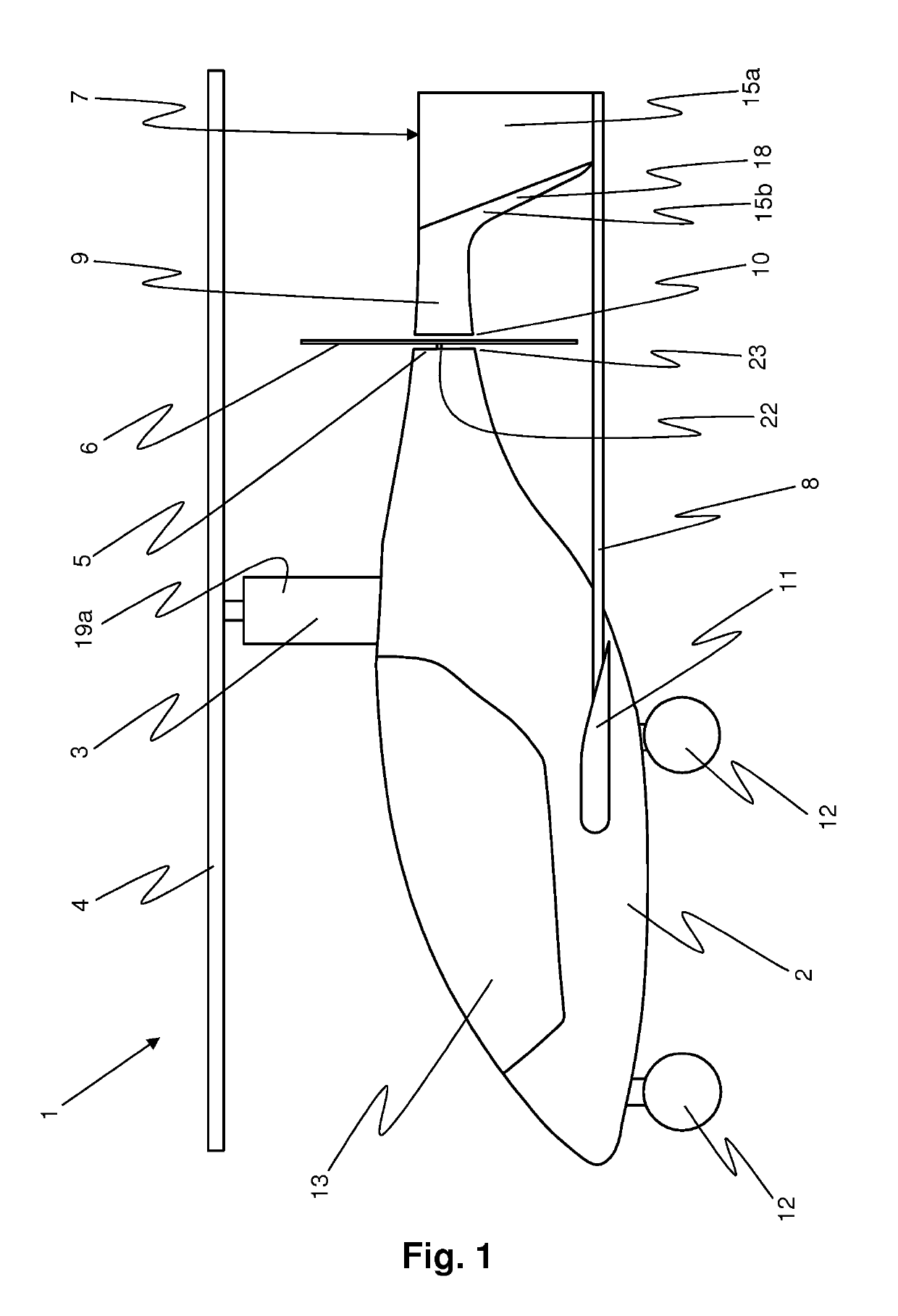
[0044]FIG. 1 shows a side view of a gyroplane 1 with a streamlined outer contour. A fuselage 2 forms the basic body of the gyroplane 1. The fuselage 2 features wheels 12 on its lower side. A passenger cabin 13 is arranged in a front area of the fuselage 2. A mast 3 is arranged in an area on the upper side of the fuselage 2. A rotor 4 is rotatably arranged at an upper end of the mast 3. The rotor 4 is set in autorotation by an air flow coming from the front and thus generates the lift of the gyroplane 1. The mast 3 transfers the lifting force from the rotor 4 to the fuselage 2.

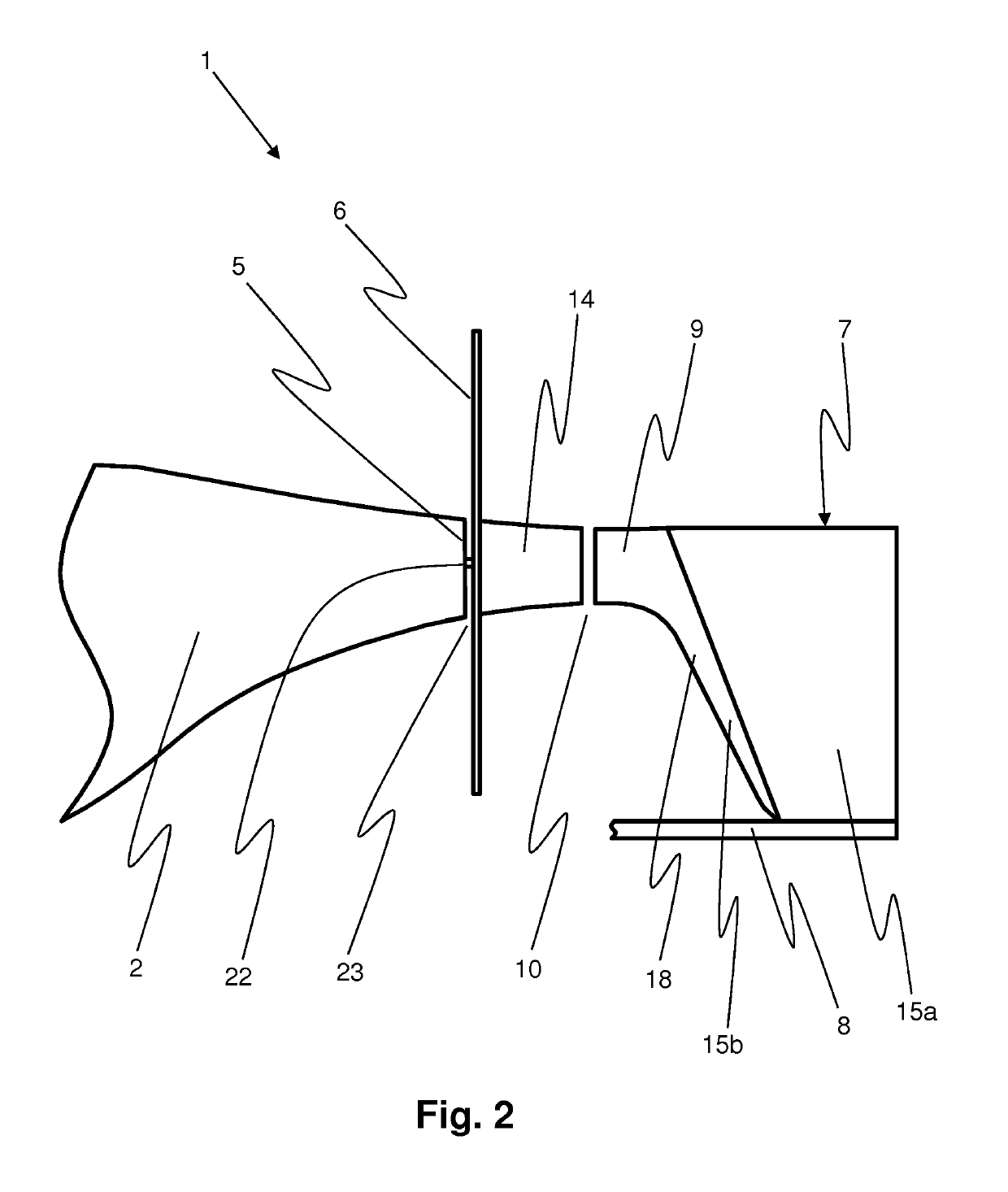
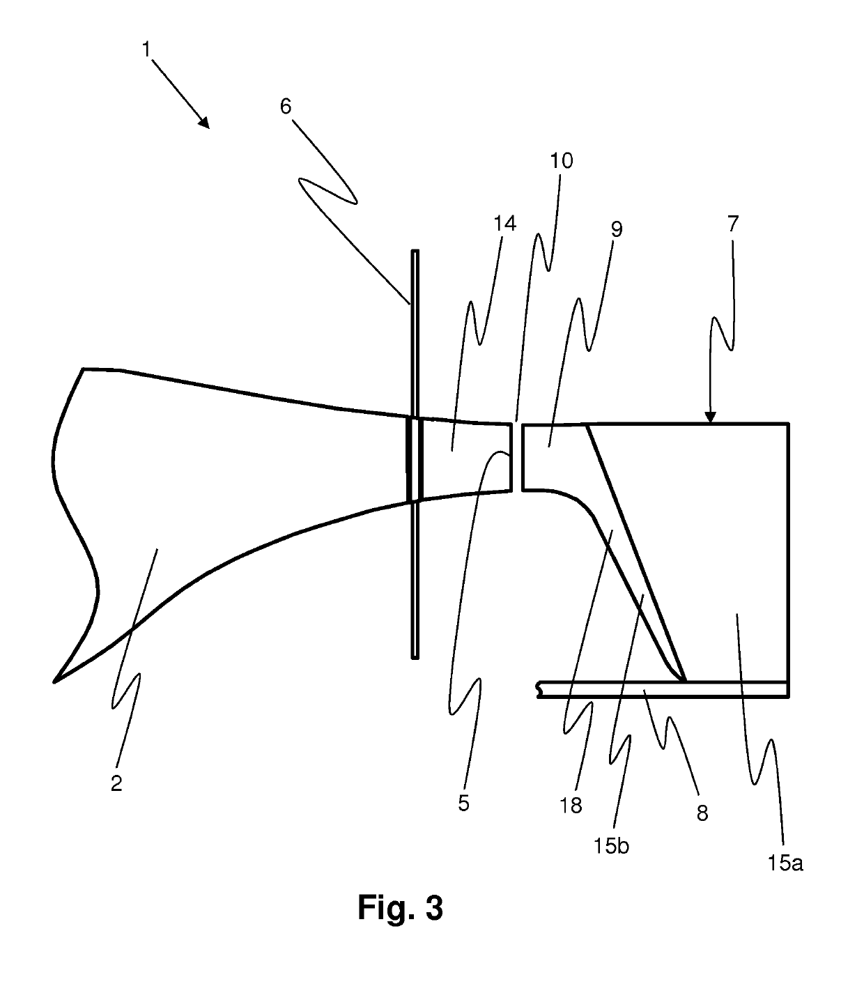
[0045]The fuselage 2 features a rear fuselage end 5. At the rear fuselage end 5, a propeller 6 is arranged, by means of which the propulsion of the gyroplane 1 can be generated. The propeller 6 is connected in a torque-proof manner to a drive shaft 22 that extends out of the fuselage 2 at the fuselage end 5. A horizontal stabilizer 7 is arranged partially behind the propeller 6 in the longitudinal direction of ...


PUM


Abstract

The invention related to an autogyro (1) comprising a body (2), a mast (3) arranged in the upper region of the body, a rotor (4) which is rotatably arranged in the region of the end of the body (3) and which can be put into autorotation by an air flow, a drivable propeller (6) which is arranged in the region of a rear body end (5) and which generates a propulsion of the autogyro (1), a guide mechanism (7) arranged behind a propeller (1), and at least one brace (8) which extends past the propeller in the longitudinal direction of the autogyro at a radial distance from the propeller (6) in an outwards direction and which connects the guide mechanism (7) to the body (2). According to the invention, the guide mechanism (7) has a guide mechanism protrusion (9) which is arranged coaxially to the rear body end (5) and which extends forwards from the guide mechanism (7) in the direction of the rear body end (5) at a distance therefrom. Furthermore, at least the region of the rear body end (5) of the body (2) and the guide mechanism protrusion (9) together form a streamlined outer contour. The invention further relates to an autogyro in which the mast (3) is designed, in particular the mast is arranged and / or inclined relative to the propeller (6), such that when rotating, the blades (17) of the propeller (6) always only partly overlap with the mast (3) in a respective overlap region (21) when viewing the autogyro (1) from the rear.

Description

FIELD OF THE INVENTION[0001]The present invention relates to a gyroplane with a fuselage, with a mast arranged in the upper area of the fuselage, and with a rotor, which can be arranged in a rotatable manner in the area of the end of the mast and can be set in autorotation by an air flow. The gyroplane also comprises a propeller that is arranged and drivable in the rear area of the fuselage, which produces the propulsion of the gyroplane, and a horizontal stabilizer arranged behind the propeller. At least one strut, which extends from the propeller, spaced from it in a radially outward direction, in the longitudinal direction of the gyroplane, connects the horizontal stabilizer to the fuselage.BACKGROUND[0002]The beginnings of gyroplanes, also known as gyrocopters or autogyros, are traced back to the 1920s; thus, they are widely known in aeronautical engineering, and are part of its basic training regarding the state of the art.[0003]A gyroplane can also be classified in the categor...

Claims


Application Information

Patent Timeline
Patent Type & Authority Patents(United States)
IPC IPC(8): B64C27/02B64C27/82
CPCB64C27/02B64C2027/8281
Inventor FRAUNDORFER, CHRISTOPH
Owner FRAUNDORFER AERONAUTICS AG
Why Eureka
Try Eureka