Tissue ligating device

a tissue ligating device and tissue technology, applied in the field can solve the problems of high difficulty, critical complication, and require a lot of skill, and achieve the effects of improving the procedure of guiding, reducing the load on operators, and improving the usability of tissue ligating devices

Active Publication Date: 2019-11-19
THE UNIV OF TOKYO
View PDF21 Cites 0 Cited by
  • Summary
  • Abstract
  • Description
  • Claims
  • Application Information

AI Technical Summary

Benefits of technology

[0016]The present inventors have extensively confirmed the usability of the tissue ligating device 100 disclosed in JP2012130669A in actual surgical operations. Meanwhile, the present inventors have felt that there is still room for improvement in the procedure of guiding the suture thread 200 to the region between the back side wall part 102B and the front side wall part 102F. Further, the present inventors have considered that such improvement leads to a remarkable reduction in the load on operators, and also in the load on patients.

Problems solved by technology

In the field of medical treatment, the procedures of suturing and ligating tissue are very important in most surgical operations, have high degree of difficulty, and require a lot of skill.
Especially difficult in the procedures of suturing and ligating tissue is the action of knotting a suture thread and thereby forming a knot.
If the knot loosens, the suture or ligation is released and that can cause a critical complication.

Method used


Image

  • Tissue ligating device
  • Tissue ligating device
  • Tissue ligating device

Examples


first embodiment

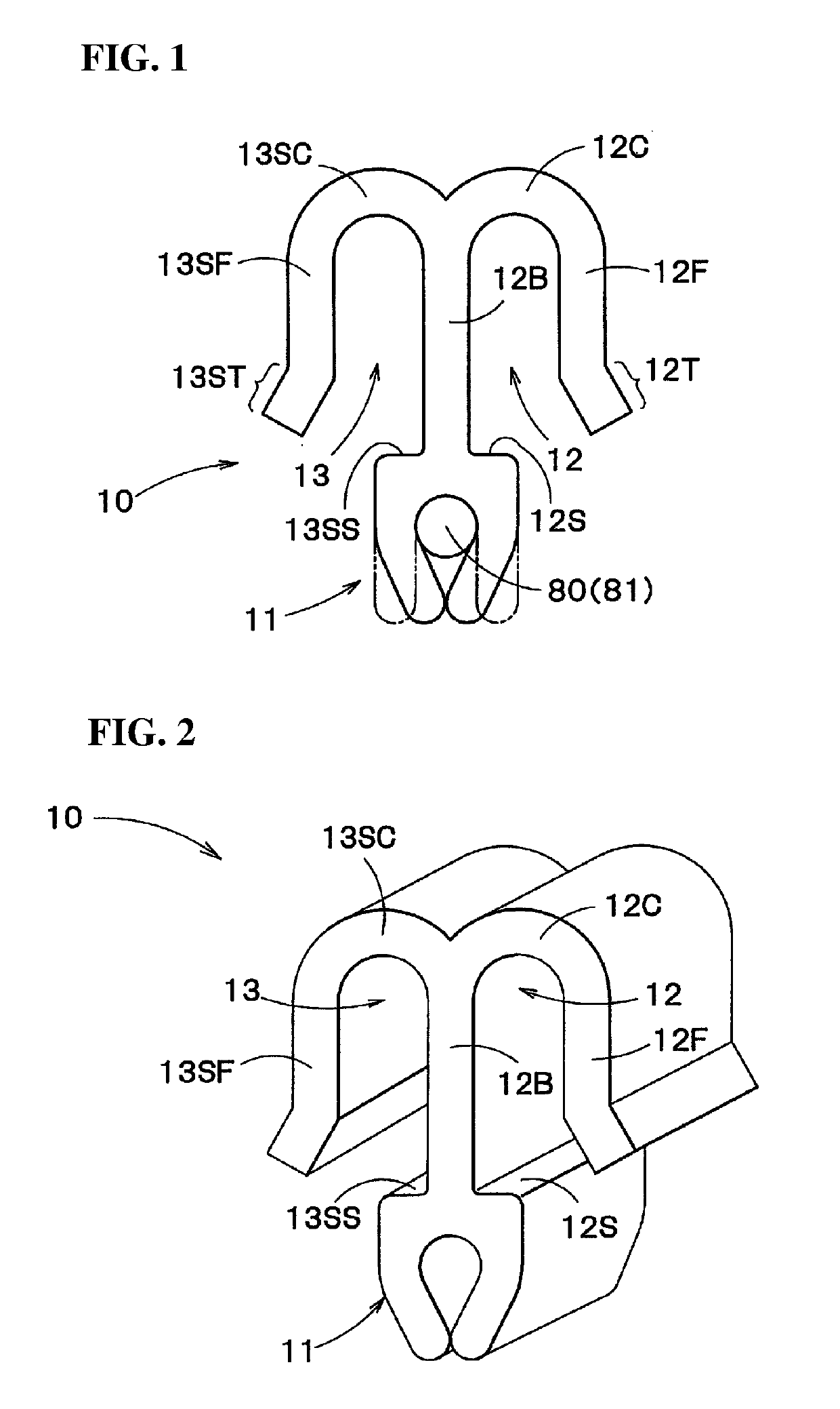
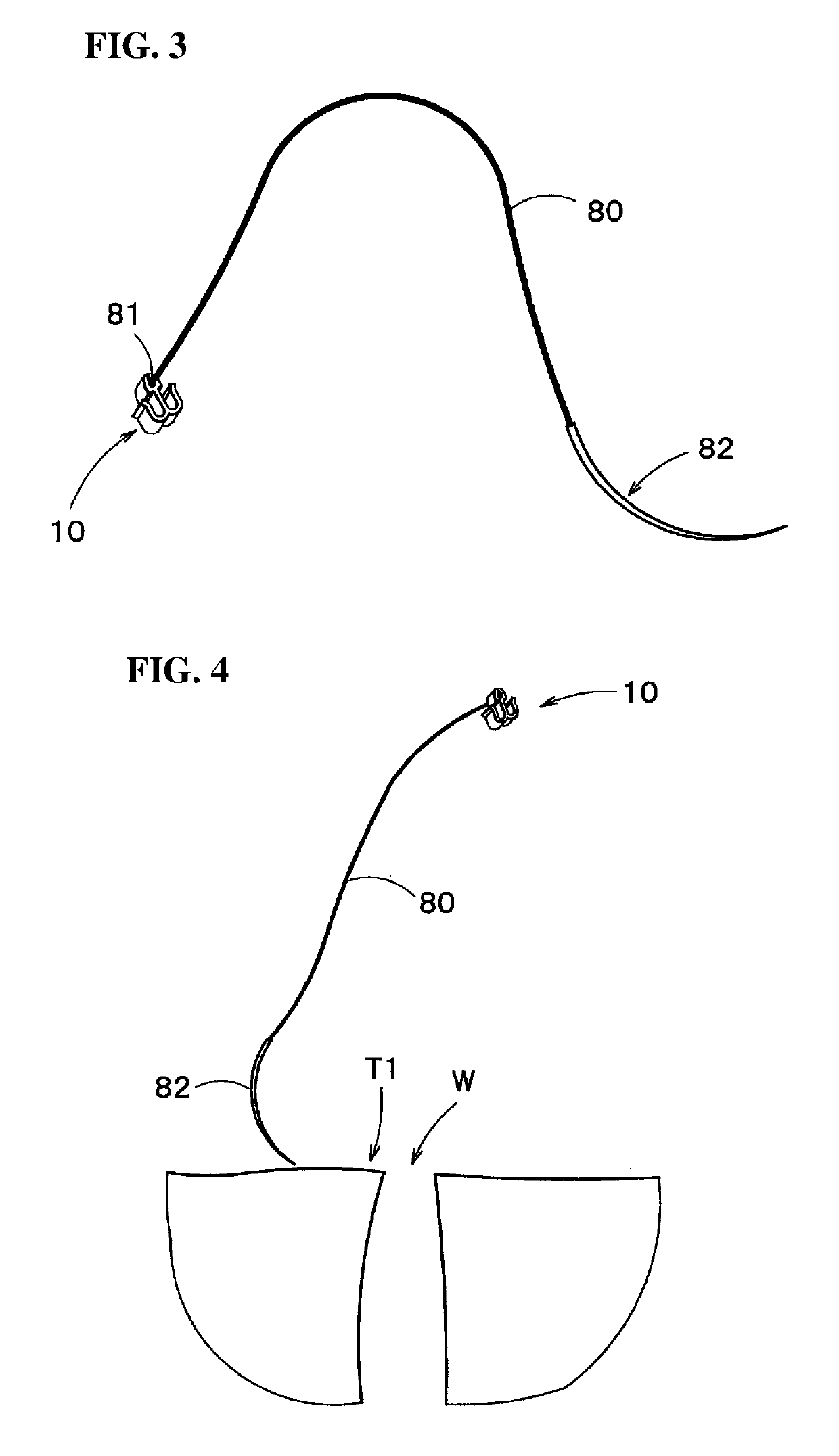
[0056]FIG. 1 is a schematic plan view showing a tissue ligating device in the present invention. FIG. 2 is a schematic perspective view showing the tissue ligating device of FIG. 1. FIG. 3 is a schematic perspective view showing a state in which a suture thread has been fixed to a first fixation part of the tissue ligating device of FIG. 1.

[0057]As shown in FIGS. 1 to 3, the tissue ligating device 10 in this embodiment includes a first fixation part 11 to which a base end part 81 of a suture thread 80 is fixed and a second fixation part 12 configured to allow insertion of the suture thread 80 therethrough and allow to be crimped so as to newly fix a part of the suture thread 80, and thereby to define a loop starting from the base end part 81, in a state after ligation of tissue is performed. A suture needle 82 is attached to a tip end part of the suture thread 80.

[0058]The first fixation part 11 in this embodiment is configured to allow insertion of the suture thread 80 therethrough...

second embodiment

[0085]Next, FIG. 11 is a schematic plan view showing a tissue ligating device in the present invention.

[0086]As shown in FIG. 11, the tissue ligating device 20 in this embodiment includes a first fixation part 21 to which a base end part 81 of a suture thread 80 is fixed and a second fixation part configured to allow insertion of the suture thread 80 therethrough and allow to be crimped so as to newly fix a part of the suture thread 80, and thereby to define a loop starting from the base end part 81, in a state after ligation of tissue is performed.

[0087]The first fixation part 21 in this embodiment is configured to allow insertion of the suture thread 80 therethrough and allow to be crimped, thereby to fix a part of the suture thread 80 as the base end part 81, in a state before ligation of tissue is performed. In FIG. 11, a state before the crimping is shown.

[0088]The second fixation part 22 in this embodiment includes a back side (left-hand side in FIG. 11) wall part 22B, a front...

third embodiment

[0104]Next, FIG. 12 is a schematic plan view showing a tissue ligating device in the present invention.

[0105]As shown in FIG. 12, the tissue ligating device 30 in this embodiment includes a first fixation part 31 to which a base end part 81 of a suture thread 80 is fixed and a second fixation part configured to allow insertion of the suture thread 80 therethrough and allow to be crimped so as to newly fix a part of the suture thread 80, and thereby to define a loop starting from the base end part 81, in a state after ligation of tissue is performed.

[0106]The first fixation part 31 in this embodiment is configured to allow insertion of the suture thread 80 therethrough and allow to be crimped, thereby to fix a part of the suture thread 80 as the base end part 81, in a state before ligation of tissue is performed. In FIG. 12, a state before the crimping is shown.

[0107]The second fixation part 32 in this embodiment includes a back side (left-hand side in FIG. 12) wall part 32B, a front...


PUM


Abstract

A tissue ligating device comprises a first fixation part to which a base end part of a suture thread is fixed and a second fixation part configured to allow insertion of the suture thread therethrough and allow to be crimped so as to newly fix a part of the suture thread, and thereby to define a loop starting from the base end part, in a state after ligation of tissue is performed. The second fixation part includes a back side wall part, a front side wall part, and a curved wall part turning back from the back side wall part to the front side wall part. An end part of the front side wall part far from the curved wall part is inclined or curved towards a front side.

Description

TECHNICAL FIELD[0001]The present invention relates to a device used in the field of medical treatment for ligating tissue.BACKGROUND ART[0002]In the field of medical treatment, the procedures of suturing and ligating tissue are very important in most surgical operations, have high degree of difficulty, and require a lot of skill.[0003]Especially difficult in the procedures of suturing and ligating tissue is the action of knotting a suture thread and thereby forming a knot. If the knot loosens, the suture or ligation is released and that can cause a critical complication.[0004]JP2012130669A discloses a tissue ligating device previously proposed by the present inventors. As shown in FIGS. 16 and 17, the tissue ligating device 100 includes a first fixation part 101 to which a base end part 201 of a suture thread 200 is fixed and a second fixation part 102 configured to allow insertion of the suture thread 200 therethrough and allow to be crimped so as to newly fix a part of the suture ...

Claims


Application Information

Patent Timeline
Patent Type & Authority Patents(United States)
IPC IPC(8): A61B17/04A61B17/122
CPCA61B17/0483A61B17/0482A61B17/0487A61B2017/0414A61B2017/0417
Inventor ONO, MINORUSAKUMA, ICHIRO
Owner THE UNIV OF TOKYO
Why Eureka
Try Eureka