Imaging device and imaging method

a technology which is applied in the field of imaging device and imaging method, can solve the problem of large operation quantity

Active Publication Date: 2020-02-04
HITACHI LTD
View PDF16 Cites 4 Cited by
  • Summary
  • Abstract
  • Description
  • Claims
  • Application Information

AI Technical Summary

Benefits of technology

[0007]According to the present invention, the operation quantity associated with development processing can be reduced. Objects, configurations, and advantageous effects other than the foregoing will be evident from the following description of embodiments.
other than the foregoing will be evident from the following

Problems solved by technology

There is a problem of requiring a large operation quantity for solving the inverse problem.

Method used


Image

  • Imaging device and imaging method
  • Imaging device and imaging method
  • Imaging device and imaging method

Examples


first embodiment

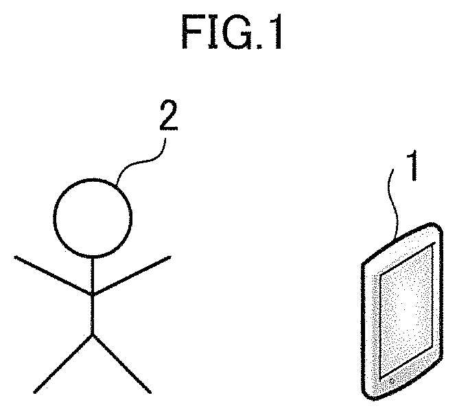
[0057]FIG. 1 is a diagram illustrating an example of a mobile terminal obtained by applying an imaging device according to a first embodiment. The mobile terminal 1 shown in FIG. 1 is, for example, a smartphone. FIG. 1 shows a subject 2 in addition to the mobile terminal 1.

[0058]The mobile terminal 1 has an imaging device (not shown). The mobile terminal 1 includes a display, and represents, on the display, a subject imaged by the imaging device.

[0059]The imaging device provided in the mobile terminal 1 is a lensless camera. More specifically, the imaging device provided in the mobile terminal 1 captures an image of the external subject 2 without using any lens for imaging. Thus, the mobile terminal 1 can be reduced in size, thickness, and weight.

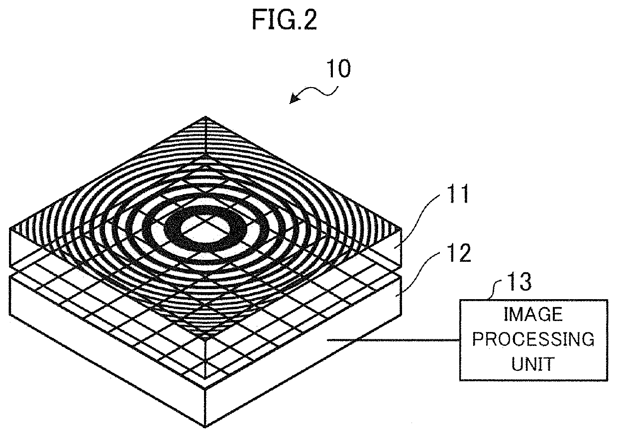
[0060]FIG. 2 is a diagram illustrating a configuration example of the imaging device provided in the mobile terminal 1. As shown in FIG. 2, the imaging device 10 has a modulator 11, an image sensor 12, and image processing unit 13.

[0061]The...

second embodiment

[0132]According to a second embodiment, Fourier transform is used as the cross-correlation operation. This reduces the operation quantity more than the convolution operation. An imaging device according to the second embodiment has the same configuration as the imaging device 10 shown in FIG. 2, but partially differs therefrom in the function of the image processing unit 13. The difference from the first embodiment will be described below.

[0133]According to the second embodiment, an image processing unit 13 applies Fourier transform to image data output from an image sensor 12. More specifically, the image processing unit 13 applies Fourier transform to the formula (5) mentioned above. The application of the Fourier transform to the formula (5) provides a result as represented by the following formula (9).

[0134][Mathematical⁢⁢Formula⁢⁢9]ℱ⁡[IF⁡(x)]=δ⁡(u)+e-iku2⁢π⁢⁢β⁢⁢sin⁢⁢(u24⁢β-ΦF+π4)(9)

[0135]Pattern data for development, subjected to Fourier transform, is stored in advance in a sto...

third embodiment

[0161]Shooting an object at infinity has been described in the first embodiment and the second embodiment. Shooting an object at a finite distance will be described in a third embodiment.

[0162]FIG. 19 is a diagram illustrating a configuration example of an imaging device 30 according to the third embodiment. In FIG. 19, the same elements as those in FIG. 2 are denoted by the same reference numerals. The differences from FIG. 2 will be described below.

[0163]As shown in FIG. 19, the imaging device 30 has an image storage device 31, an image processing unit 32, and a focusing unit 33.

[0164]The image storage device 31 stores image data output from the image sensor 12.

[0165]The image processing unit 32 has a function similar to the image processing unit 13 shown in FIG. 2, but differs therefrom in terms of generation of pattern data for development. More specifically, the image processing unit 32 has no pattern data for development stored in advance in any storage device.

[0166]The focusi...


PUM


Abstract

An imaging device includes: a modulator with a first pattern, which is configured to modulate light intensity; an image sensor configured to convert light passing through the modulator to image data, and output the image data; and an image processing unit configured to restore an image on the basis of cross-correlation operation with the image data and pattern data that represents a second pattern.

Description

CLAIM OF PRIORITY[0001]This application claims the priority based on the Japanese Patent Application No. 2016-196270 filed on Oct. 4, 2016. The entire contents of which are incorporated herein by reference for all purpose.BACKGROUNDTechnical Field[0002]The present invention relates to an imaging device and an imaging method.Related Art[0003]There is a need for digital cameras mounted on smartphones and the like to be reduced in thickness. Techniques for reduction in thickness for this type of digital cameras include, for example, techniques for obtaining object images without the use of any lens (see the U.S. Patent Application Publication No. 2014 / 0253781, for example).[0004]According to the U.S. Patent Application Publication No. 2014 / 0253781, a grating pattern is formed at the upper surface of a substrate attached onto an image sensor. This grating pattern is a special pattern such as a spiral pattern. Further, according to the U.S. Patent Application Publication No. 2014 / 0253781...

Claims


Application Information

Patent Timeline
Patent Type & Authority Patents(United States)
IPC IPC(8): G02B5/18G02B27/00H04N5/225H04N5/232H04N5/369
CPCG02B27/0037G02B5/1871G02B27/0068G02B27/0087H04N5/23232H04N5/2254G02B5/1842H04N5/3696H04N5/23245H04N23/54H04N23/55H04N25/702G06T2200/21H04N23/80H04N23/667H04N23/951
Inventor NAKAMURA, YUSUKESHIMANO, TAKESHI
Owner HITACHI LTD
Why Eureka
Try Eureka