Supercharge Your Innovation With Domain-Expert AI Agents!

Structural object having substrate surfacially protected and integrally clad with metallic glass sheet

a technology of metallic glass and substrate, applied in the direction of synthetic resin layered products, packaging, pipes, etc., can solve the problems of limiting the use of industrial and commercial purposes, improper sputtering process and apparatus, and limited on-site service, so as to reduce the drag of the conduit skin, and reduce the drag of the conduit. , the effect of increasing the fluid velocity

Active Publication Date: 2020-02-18
TAICHI METAL MATERIAL TECH LTD
View PDF3 Cites 0 Cited by
  • Summary
  • Abstract
  • Description
  • Claims
  • Application Information

AI Technical Summary

Benefits of technology

[0007]The object of the present invention is to provide a structural object including a substrate integrally clad with a metallic glass sheet by adhering, welding or joining the metallic glass sheet on the substrate for a low-cost, flexible and convenient fabrication, assembly, processing or construction of the object.
[0008]Another object of the present invention is to provide a metallic-glass clad conduit having a micro-turbulent boundary layer formed as a micro-structure surface in an inner surface of the metallic-glass sheet as cylindrically formed in the fluid conduit in order to reduce a skin drag of the conduit, thereby increasing the fluid velocity of a fluid flowing in the conduit.
[0009]Still another object of the present invention is to provide a hull or housing (such as of a ship or under-water equipment) including a metallic glass sheet having a micro-structured surface and clad on a substrate of the hull or housing and having an electrical pulse generating circuit formed on the metallic glass sheet for producing electrical pulses or acoustical shock waves for preventing biofouling on the hull or housing surface by organisms or barnacles, thereby well protecting the hull or housing, increasing the ship coursing speed, reducing the fuel consumption, and improving corrosion resistance.

Problems solved by technology

So, such a sputtering process can only be performed within a fixed chamber for coating MGTF on a substrate, not suitable for coating metallic glass on a substrate of an object or structure already built in a construction site or place, thereby limiting its industrial and commercial uses.2. For coating a gigantic structure or long-distance object with MGTF, such a sputtering process and apparatus will be improper and will be greatly limited for its on-site service.
For example, if it is intended to coat a long pipe with MGTF, a great difficulty to build and operate such a big sputtering apparatus will be encountered.

Method used


Image

  • Structural object having substrate surfacially protected and integrally clad with metallic glass sheet
  • Structural object having substrate surfacially protected and integrally clad with metallic glass sheet
  • Structural object having substrate surfacially protected and integrally clad with metallic glass sheet

Examples


Embodiment Construction

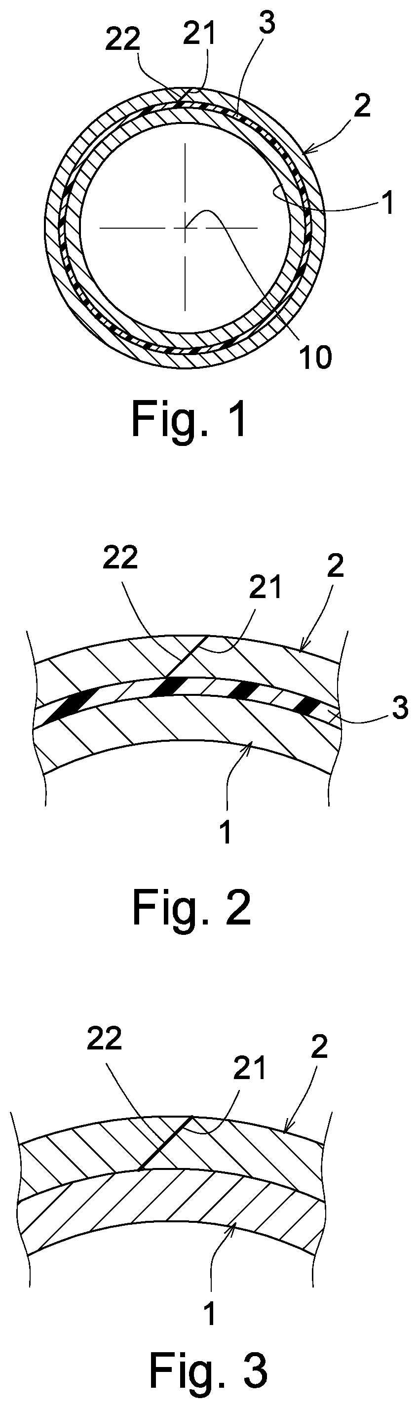
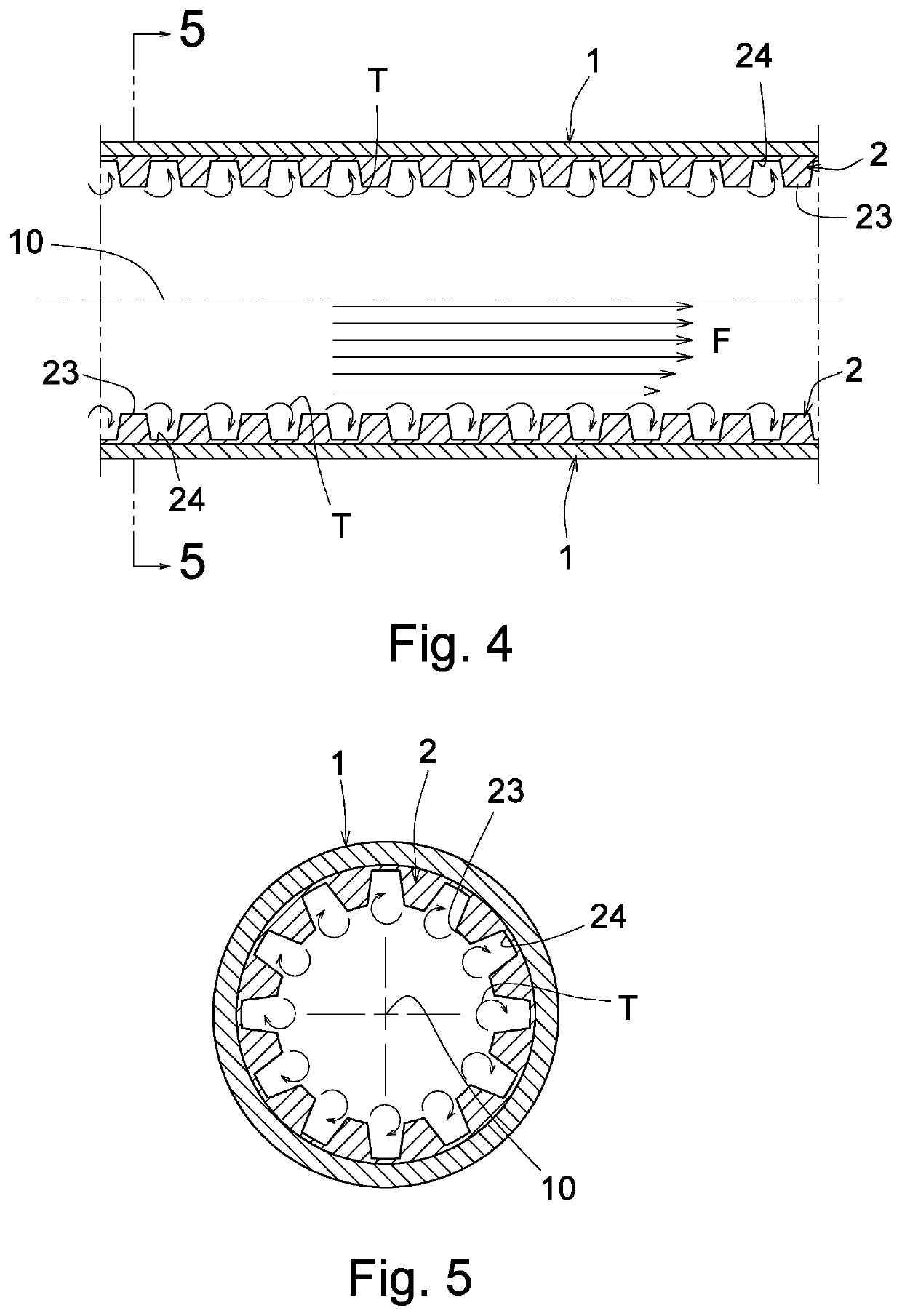
[0018]The present invention comprises a structural object or object having a substrate 1 clad with a metallic glass sheet 2 on a surface of the substrate 1. The present invention also comprises a process for making such an object having metallic glass sheet clad on a substrate of the object.

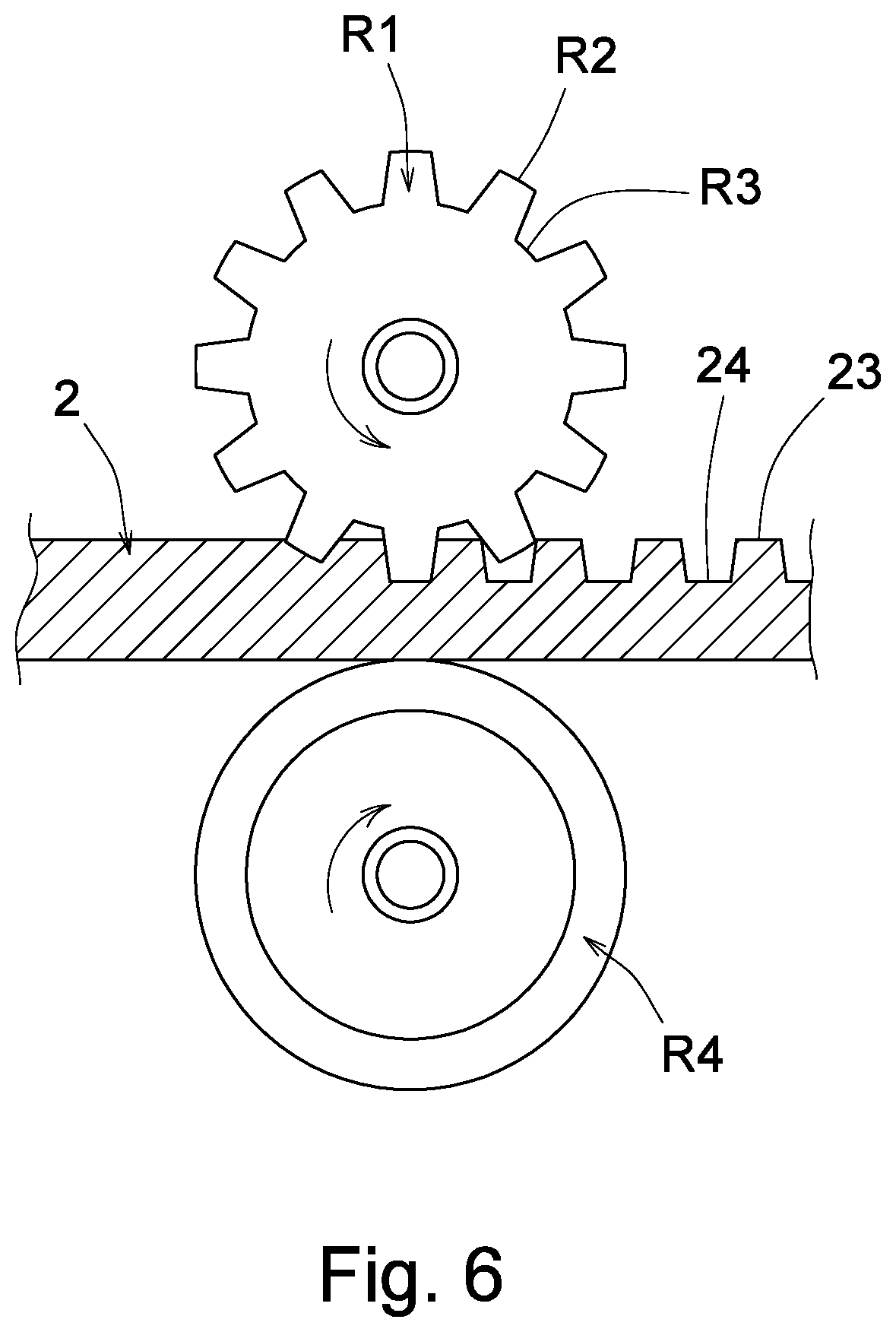
[0019]A metallic glass sheet is made by feeding molten alloy of metallic glass through a pair of cooling wheels for rapidly cooling the molten alloy into metallic glass sheet. The thickness of the metallic glass sheet can be adjusted by adjusting the gap between the two cooling wheels. Each metallic glass sheet may have a thickness of several microns to hundreds of microns, not limited in the present invention.

[0020]The “sheet” of metallic glass as defined in the present invention may also be referred to a metallic glass piece, strip, strap, band, fabric or layer, not limited in this invention.

[0021]The “object” of the present invention may refer to a pipe, a beam (such as 1 beam) of building mat...


PUM

PropertyMeasurementUnit
metallicaaaaaaaaaa
velocityaaaaaaaaaa
hardnessaaaaaaaaaa

Abstract

A structural object includes a substrate integrally clad with a metallic glass sheet by adhering, welding or joining the metallic glass sheet on the substrate for a low-cost, flexible and convenient fabrication, assembly, processing or construction of the object.

Description

BACKGROUND OF THE INVENTION[0001]It is known that metallic glass has the advantageous properties, including: high hardness, high fracture strength, high yield strength and, high corrosion resistance.[0002]So, a substrate may be coated with a metallic glass thin film to increase its mechanical properties for engineering uses.[0003]U.S. Pat. No. 9,339,990 disclosed a Zr-based or Zr—Cu based metallic glass thin film (MGTF) coated on an aluminum alloy substrate to improve many mechanical properties of the MGTF coated aluminum alloy substrate by using a sputtering process, which however has the following drawbacks:[0004]1. When performing the sputtering, the metal glass target serves as a cathode and the substrate, having a buffering layer thereon for sputtering, serves as an anode, and a DC magnetron sputter machine is provided to form the metallic glass thin film on the substrate. A chamber for the sputtering should be vacuumed, and then directed with argon gas into the chamber. So, su...

Claims


Application Information

Patent Timeline
Patent Type & Authority Patents(United States)
IPC IPC(8): B32B1/08B32B5/14B32B15/085B32B1/02B32B15/08B63B59/04B32B15/092B32B15/082B32B15/01B32B1/00F15D1/06F15D1/00F16L9/14C22C1/00
CPCF15D1/06F15D1/005B32B5/14B32B15/08B32B15/082F16L9/14B63B59/045B32B15/085B32B15/092B32B5/145B32B15/01B32B1/02B32B1/00B32B1/08B63B2231/70B63B2231/02C22C1/002B32B3/30B32B15/14B32B15/18B32B2307/546B32B9/047B32B2307/714B32B2255/205B32B5/26B32B2262/101B32B3/28B32B2605/00B32B27/12B32B2307/554B32B2597/00B32B2307/732B32B7/12B32B7/09B32B2250/02B32B9/005B32B2419/00B32B2439/00B32B2307/536B32B5/024B32B2307/304B32B2605/12B32B17/06C22C1/11
Inventor CHEN, KUAN-WEI
Owner TAICHI METAL MATERIAL TECH LTD
Features
  • R&D
  • Intellectual Property
  • Life Sciences
  • Materials
  • Tech Scout
  • Unparalleled Data Quality
  • Higher Quality Content
  • 60% Fewer Hallucinations
Learn More