Injection device

a technology of injection device and stent, which is applied in the direction of medical devices, intravenous devices, medical devices, etc., can solve the problems of ineffective latching installation, and achieve the effect of high operating comfor

Active Publication Date: 2020-05-12
HASELMEIER SARL
View PDF26 Cites 0 Cited by
  • Summary
  • Abstract
  • Description
  • Claims
  • Application Information

AI Technical Summary

Benefits of technology

[0003]It is an object of the invention to provide an injection device which has a higher level of operating comfort.
[0008]An advantageous, simple configuration results when the operating element has at least one latching web, wherein the at least one latching web in the first position of the operating element forms part of the first coupling, and in the second position of the operating element forms part of the second latching installation. The latching web thus has a dual function. A simple and compact construction results on account thereof.

Problems solved by technology

A latching installation is not effective when the components between which the latching installation acts do not move relative to one another in the latching direction such that no latching noises are generated and the elements are adjusted in latching steps.

Method used


Image

  • Injection device
  • Injection device
  • Injection device

Examples


Embodiment Construction

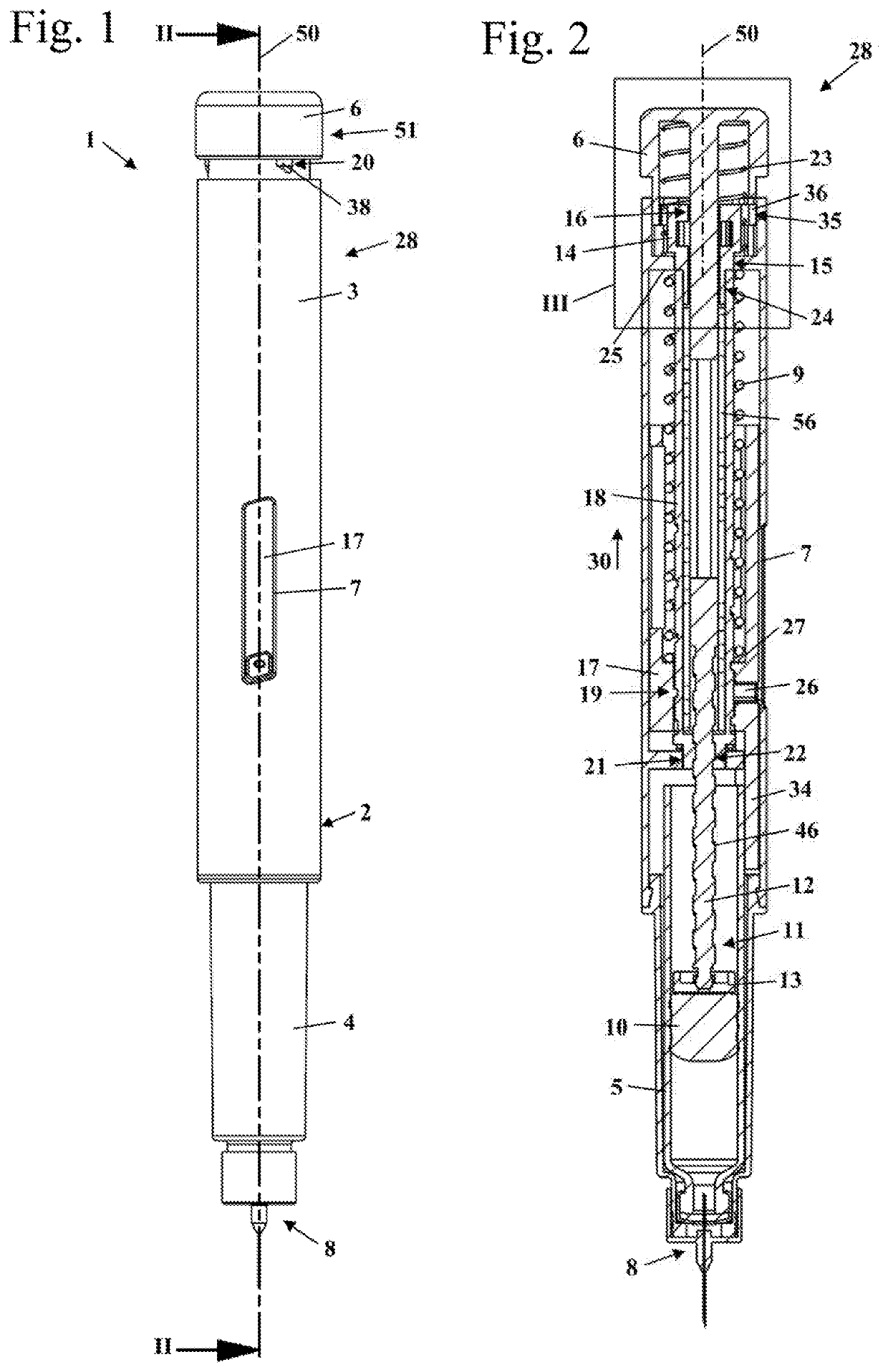
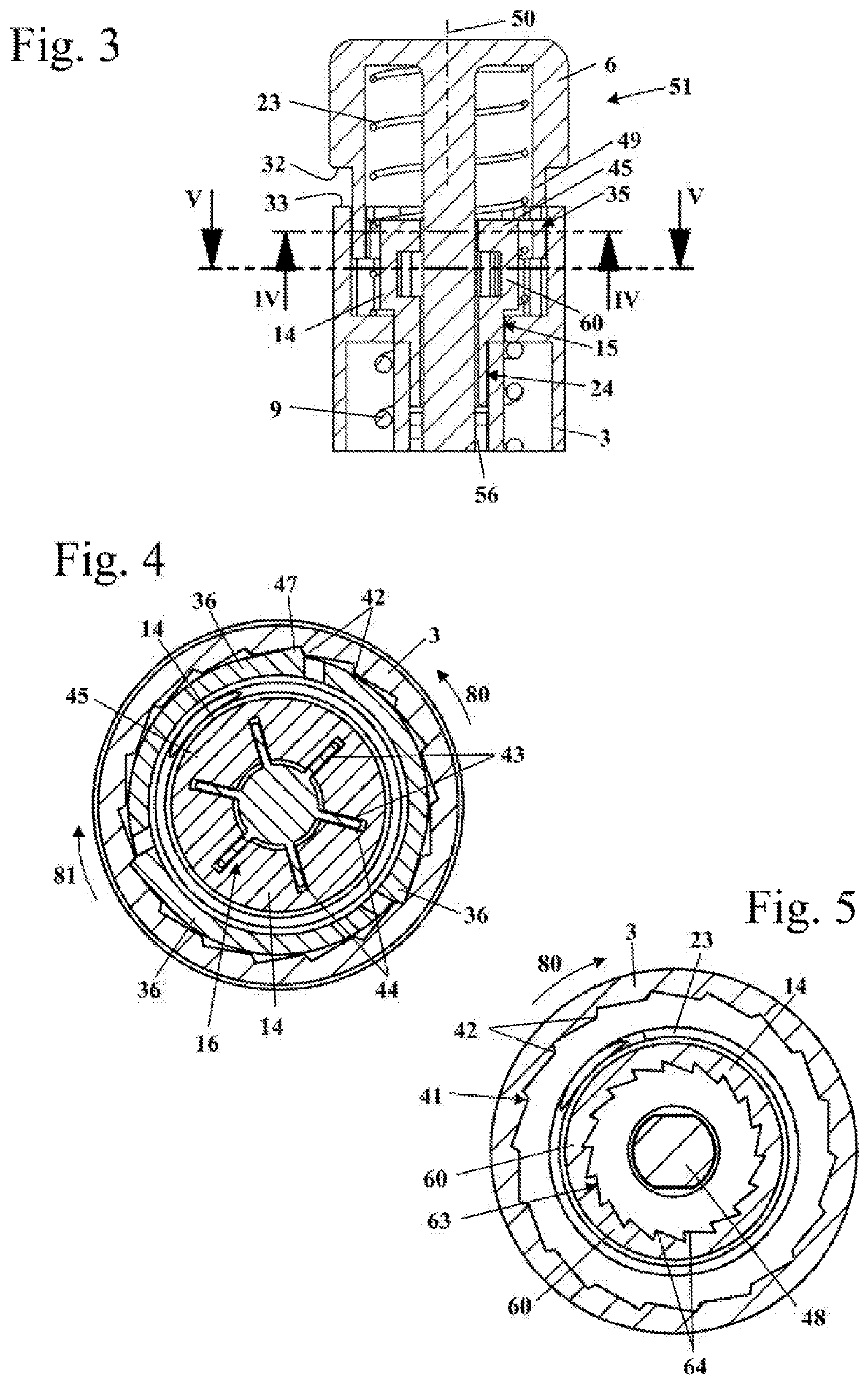
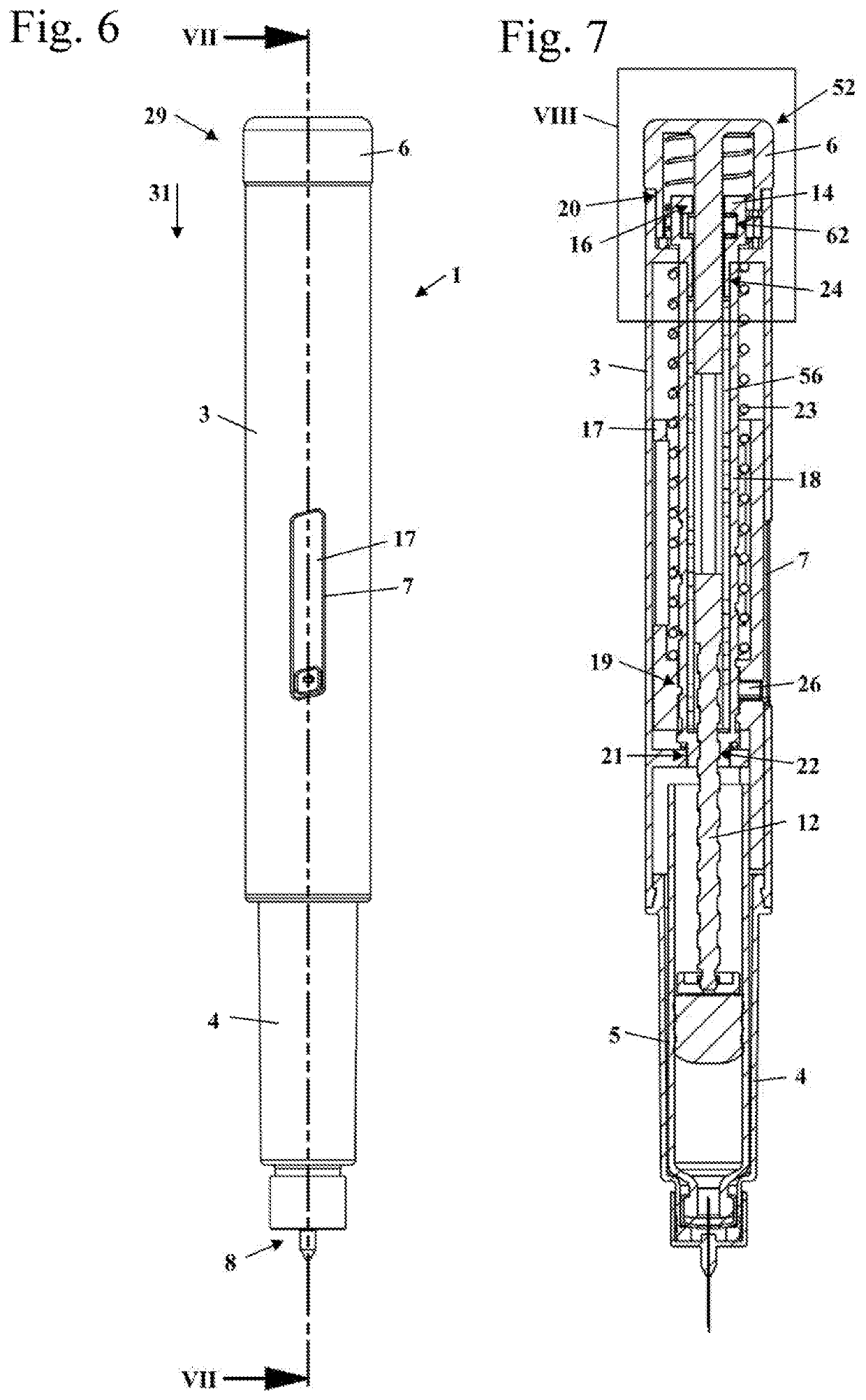
[0041]FIG. 1 shows an injection device 1 in a lateral view. The injection device 1 is a mechanical injection device in which the squeezing out of a dosage of injection liquid is performed automatically upon the activation of a release element. The injection device 1 has a housing 2 which comprises an upper housing part 3 and a holder 4 which is secured on an upper housing part 3. The holder 4 is disposed on a proximal side of the upper housing part 3. An injection needle 8 is secured on the proximal side of the holder 4. “Proximal” herein refers to that side of the injection device 1 which in an injection faces the pierced location, and “distal” refers to that side that faces away from the pierced location. The distal end of the injection device 1 is that end that faces away from an injection needle 8 that is held on the injection device 1. The proximal direction describes the injection direction, thus the direction toward the injection needle 8, or the direction in which the inject...


PUM


Abstract

An injection device includes: a housing defining a longitudinal axis; an operating element; a metering member held in the housing so as to be rotatable and fixed in the direction of the axis; the operating element, in a first position for setting a quantity to be dispensed, being mounted so as to be rotatable relative to the housing and rotationally fixedly connected to the metering member via a first coupling; the operating element, in a second position for dispensing, being rotationally fixedly connected to the housing via a second coupling and being rotatable in relation to the metering member; a first latching installation acting between operating element and housing, wherein the first latching installation is effective only in the operating element's first position; and, a second latching installation acting between operating element and metering member, wherein the second latching installation is effective only in the operating element's second position.

Description

CROSS REFERENCE TO RELATED APPLICATIONS[0001]This application is a continuation application of international patent application PCT / EP2016 / 001600, filed Sep. 26, 2016, designating the United States and claiming priority from German application 20 2015 006 841.3, filed Sep. 30, 2015, and the entire content of both applications is incorporated herein by reference.BACKGROUND OF THE INVENTION[0002]An injection device of the generic type in which an operating element is rotated in relation to the housing in order for a quantity of injection liquid to be squeezed out to be set is known from DE 20 2012 001 411 U1. A metering member that is rotatably mounted in the housing is conjointly rotated herein. A latching installation acts between the operating element and an injection sleeve that is rotatably mounted in the housing. A second latching insulation acts between the housing and a metering member rotatably mounted in the housing. Both latching installations are effective when setting a q...

Claims


Application Information

Patent Timeline
Patent Type & Authority Patents(United States)
IPC IPC(8): A61M5/315A61M5/31A61M5/20
CPCA61M5/31535A61M5/2033A61M5/20A61M5/31583A61M5/31553A61M2205/582A61M2005/3126A61M2205/581A61M5/3157
Inventor KEITEL, JOACHIM
Owner HASELMEIER SARL
Why Eureka
Try Eureka