Locking device for high-voltage switchgear

a high-voltage switch and lock technology, applied in the direction of contact driving mechanism, electrical apparatus, contact mechanism, etc., can solve the problems of increasing the cost and the space required for the actuating devi

Active Publication Date: 2017-02-16
HITACHI ENERGY SWITZERLAND AG
View PDF3 Cites 7 Cited by
  • Summary
  • Abstract
  • Description
  • Claims
  • Application Information

AI Technical Summary

Benefits of technology

[0013]The locking device according to the invention is simple and compact and can also be easily retrofitted into the high-voltage switchgear. The locking device makes it possible for trained, authorized personnel to lock or unlock, on-site, the access for a manual actuation of the two switching devices or the access for an actuation of the two switching devices with the aid of motors which are controlled from a remotely located control room. The locking device, having the slider on one side and the rocker bar arrangement and the closing disk on the other side, comprises two mechanical components which can be actuated independently of one another, but which cooperate with one another during a locking process or an unlocking process during operation of the high-voltage switchgear. Given that the slider and the rocker bar arrangement are actuated independently of one another, the slider can be used to activate or block, on-site, the access for the remote actuation or for the on-site actuation of the two switching devices. After the access for the on-site actuation has been activated, the two switching devices can be unlocked, on-site, using the rocker bar arrangement, and can then be manually moved into the neutral position or into one of the two active positions using a crank handle, and can then be locked using the rocker bar arrangement and the closing disk. Since only simple and robust mechanical components, such as the slider, the closing disk, and the rocker bar arrangement, are required therefor, the locking device according to the invention, which has a simple and compact design, is distinguished by a high level of operating comfort and great operational safety.

Problems solved by technology

This increases the costs and the amount of space required for the actuating device.

Method used


Image

  • Locking device for high-voltage switchgear
  • Locking device for high-voltage switchgear
  • Locking device for high-voltage switchgear

Examples


Embodiment Construction

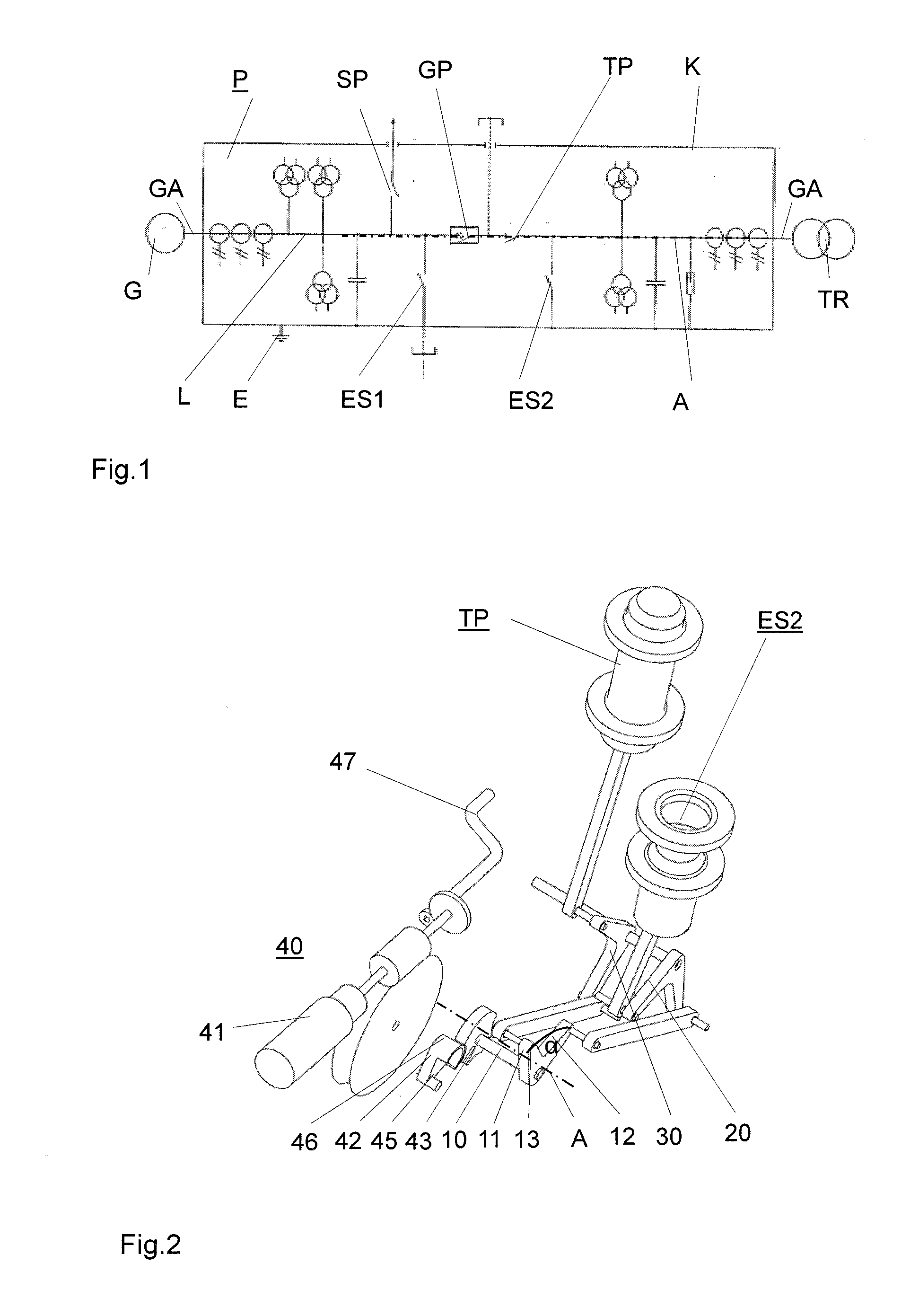
[0036]The multi-phase generator circuit-breaker system represented as a single phase in FIG. 1 shows only one of several largely similarly designed circuit-breaker system poles P which are oriented parallel with one another and parallel with a horizontally extending axis A. The poles are arranged in a horizontally extending plane and are connected along a generator lead GA, which is oriented along the axis, between a generator G of a power plant and a transformer TR of a high-voltage transmission network. The pole P which is shown is single-phase and enclosed and has an encapsulation K which is generally made from metal, is electrically conductively routed to ground E, and is filled with ambient air. The encapsulation K accommodates a phase conductor L which is routed parallel to the axis A and in which a circuit-breaker pole GP of a multi-phase generator circuit-breaker and a circuit-breaker pole TP of a multi-phase disconnect switch are connected in series. A connection point of t...


PUM


Abstract

The device is used for locking an access for actuating two switching devices of high-voltage switchgear with the aid of a drive shaft transmitting drive force onto the two switching devices. In order to increase the operational safety of the high-voltage switchgear with little outlay, the locking device comprises a closing disk which is fastened on the drive shaft, a rocker bar arrangement containing at least four rocker bars, and a slider. The slider can be moved, on-site, into two positions, the first of which releases an access for the actuation on-site and blocks an access for the actuation from a remote location, and the second of which blocks the access for the on-site actuation and releases the access for the remote actuation.

Description

TECHNICAL FIELD[0001]The present invention relates to a device for locking an access for actuating two switching devices of high-voltage switchgear according to the introductory part of claim 1.[0002]The high-voltage switchgear contains an actuating device which transfers drive force from a drive shaft to a contact arrangement of a first of the two switching devices and to a contact arrangement of a second of the two switching devices. The two switching devices have different functions and are generally suitable for connecting or disconnecting currentless or nearly currentless electric circuits. Such switching devices are frequently used as a disconnect switch / grounding switch system on the transformer side or as a start-up switch / grounding switch system on the generator side of high-voltage switchgear which is designed as a generator circuit-breaker system and is then typically operated at nominal voltages between a few kV and 70 kV to 80 kV. However, they can also be used in gas-i...

Claims


Application Information

Patent Timeline
Patent Type & Authority Applications(United States)
IPC IPC(8): H01H27/06
CPCH01H27/06H01H2300/018H01H2239/044H01H9/26H01H3/227H01H3/44H01H9/24H01H9/282H01H9/285
Inventor CHENG, DANIEL-JUNLI, JAMES-SHENG QIANGWANG, JIANMEINEUBAUER, SEVERINWIDENHORN, MARKUS
Owner HITACHI ENERGY SWITZERLAND AG
Why Eureka
Try Eureka