Electric brake system and method for controlling the same

a technology of brake system and brake plate, which is applied in the direction of brake system, asr control system, braking components, etc., can solve the problems of large wheel pressure variation, unavoidable error, and brake pressure occurrence, so as to reduce not only noise and vibration, and finish stably

Active Publication Date: 2020-05-19
HL MANDO CORP
View PDF11 Cites 0 Cited by
  • Summary
  • Abstract
  • Description
  • Claims
  • Application Information

AI Technical Summary

Benefits of technology

[0010]Therefore, it is an aspect of the present disclosure to provide a technology for reducing not only noise and vibration generated in the end of ABS control, but also driver's sense unfamiliar with ABS braking of a vehicle, and stably finishing the ABS control.
[0017]When a difference between brake pressure requested by the driver and pressure of at least one wheel is higher than a predetermined threshold value, the controller may calculate the change amount of stroke of the piston in a manner that brake pressure corresponding to the driver's braking intention, and may acquire the calculated stroke change amount so as to boost the pressure of each wheel at a predetermined slope.

Problems solved by technology

In this case, the brake pressure may allow rotational force of the motor to be converted into rectilinear motion and presses a piston, resulting in the occurrence of brake pressure.
In this case, when the electronically controlled brake system regulates wheel valves during ABS control, there may occur a large variation in wheel pressure, such that an unexpected error may unavoidably occur between brake pressure requested by a vehicle driver and actual pressure generated in wheels at the end point of the ABS control.

Method used


Image

  • Electric brake system and method for controlling the same
  • Electric brake system and method for controlling the same
  • Electric brake system and method for controlling the same

Examples


Embodiment Construction

[0032]Reference will now be made in detail to the embodiments of the present disclosure, examples of which are illustrated in the accompanying drawings, wherein like reference numerals refer to like elements throughout. The scope or spirit of the present disclosure is not limited to the embodiments and may be realized in various other forms. The embodiments are only provided to more completely illustrate the present disclosure and to enable a person having ordinary skill in the art to fully understand the scope of the present disclosure. In the drawings, sizes and shapes of elements may be exaggerated or reduced for convenience and clarity of description.

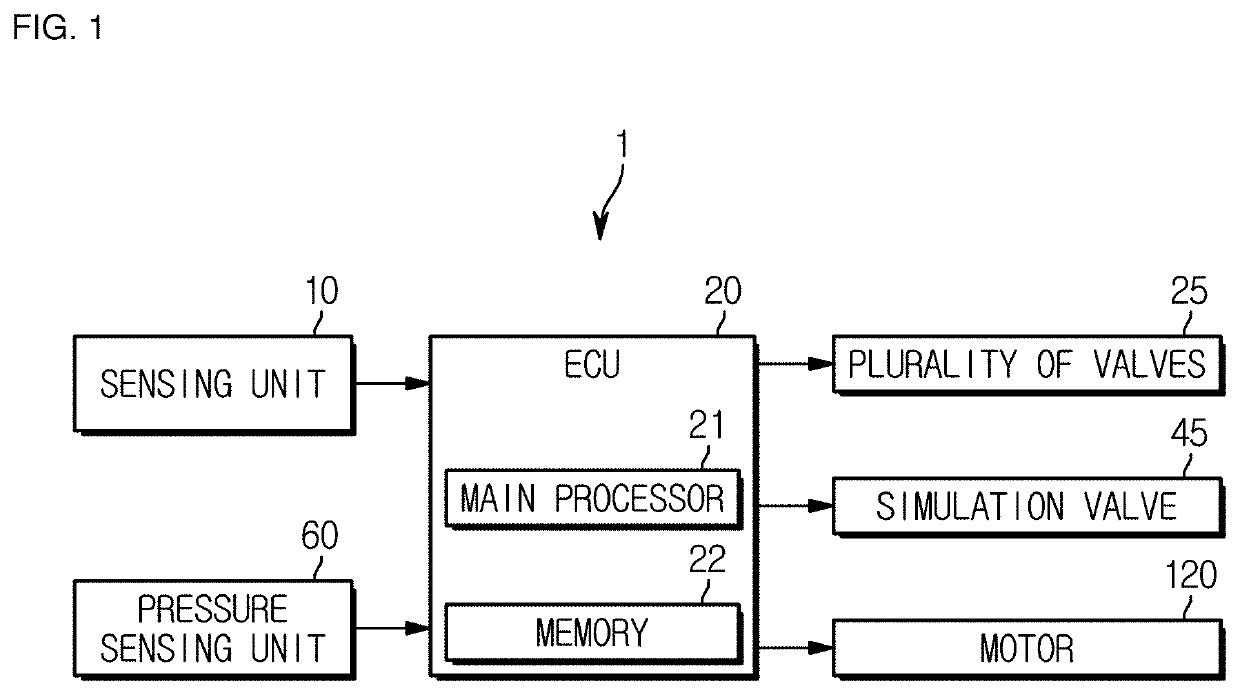
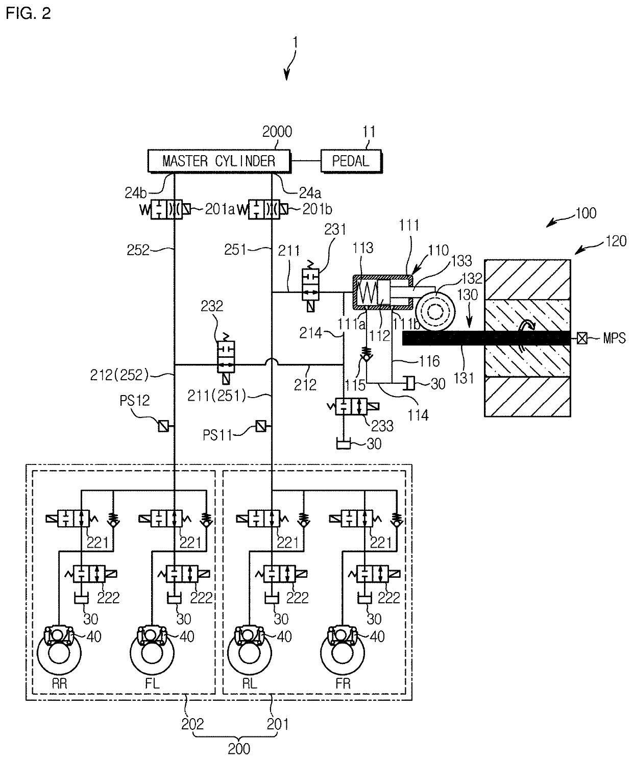
[0033]FIG. 1 is a block diagram illustrating an electric brake system of a vehicle according to an embodiment of the present disclosure. FIG. 2 is a view illustrating a hydraulic circuit controlled by the electric brake system of the vehicle according to the embodiment of the present disclosure.

[0034]Referring to FIG. 1, the electri...


PUM


Abstract

An electric brake system and a method for controlling the same are disclosed. The electric brake system includes a hydraulic control device, a sensing unit, and a controller. The hydraulic control device generates hydraulic pressure using a piston operated by an electric signal generated in response to a displacement of a brake pedal. The sensing unit detects driver's braking intention. When an electronic stability control (ESC) of a vehicle operates, the controller calculates a change amount of stroke of the piston needed to output brake pressure corresponding to the driver's braking intention, and acquires the calculated stroke change amount so as to boost pressure of each wheel at a predetermined slope.

Description

CROSS-REFERENCE TO RELATED APPLICATION[0001]This application is based on and claims priority under 35 U.S.C. § 119 to Korean Patent Application No. 10-2017-0052327, filed on Apr. 24, 2017 in the Korean Intellectual Property Office, the disclosure of which is incorporated by reference in its entirety.BACKGROUND1. Field[0002]Embodiments of the present disclosure relate to an electric brake system, and more particularly to an electric brake system for regulating hydraulic pressure to stably stop operation of an anti-lock brake system (ABS), and a method for controlling the same.2. Description of the Related Art[0003]A brake system for braking of a vehicle is essentially mounted to a vehicle, and various systems have recently been proposed to obtain stronger and more stable braking force.[0004]Examples of brake systems include anti-lock brake systems (ABSs) to prevent slippage of wheels during braking, brake traction control systems (BTCSs) to prevent slippage of driving wheels during s...

Claims


Application Information

Patent Timeline
Patent Type & Authority Patents(United States)
IPC IPC(8): B60T8/32B60T13/74B60T13/66B60T13/62B60T8/48B60T8/176B60T8/1755B60T8/175B60T8/172B60T7/04B60T8/40
CPCB60T8/4081B60T13/662B60T13/745B60T8/3275B60T7/042B60T8/175B60T8/4827B60T8/172B60T13/62B60T8/176B60T8/4072B60T8/1755B60T2270/82B60T2220/04B60T2270/10B60T2270/304B60T2270/20B60T8/17B60T13/66B60T13/741B60T13/686B60Y2400/81
Inventor KIM, YOUNG-JAE
Owner HL MANDO CORP
Why Eureka
Try Eureka