Additive manufacturing of discontinuous fiber composites using magnetic fields
a technology of discontinuous fiber and composites, applied in the directions of additive manufacturing processes, manufacturing tools, transportation and packaging, etc., can solve the problems of limited robotic placement printers, lightweight printed polymers, and relatively weak printing properties
- Summary
- Abstract
- Description
- Claims
- Application Information
AI Technical Summary
Benefits of technology
Problems solved by technology
Method used
Image
Examples
example 1
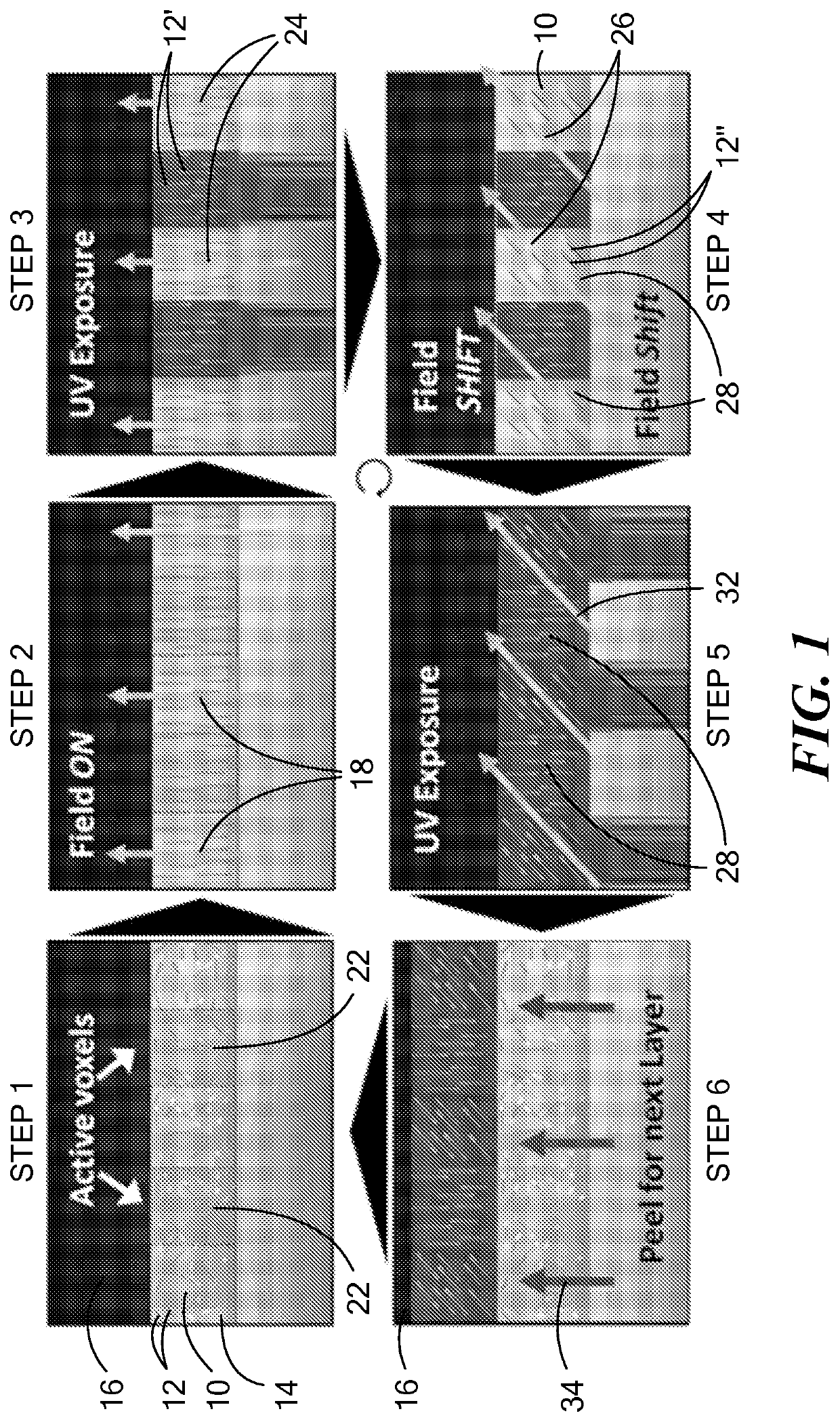
[0171]The feasibility of aligning microscopic particles using magnetic assembly polymer matrices was evaluated with UV curable resins due to their low viscosity and controllable polymerization. Tests were conducted on an N-Scrypt 3Dn table top series modified with a 365 nm light source. A permanent magnet was employed to apply a magnetic field in different directions. Two different fillers were investigated: calcium phosphate rods and alumina (Al2O3) platelets. The resin system employed was alkoxylated pentaerythritol tetraacrylate (Sartomer) with 1 wt % Irgacure 184 (Ciba, Transparent photoinitiator), ˜1% volume Al2O3 platelets or calcium phosphate rods. Samples were made using both a stereolithography (SLA) technique by aligning particles in a container filled with resin and a technique of aligning particles while printing with a micro-nozzle.
[0172]Particles aligned in the bulk resin container were allowed 5 minutes to align in the magnetic field before polymerization. For the pri...
examples 2-4
[0175]Magnetically responsive reinforcing particles were prepared as follows: Alumina (Al2O3) platelets (obtained from Allusion) were electrostatically coated with approximately 5% surface coverage superparamagnetic iron oxide (Fe3O4) nanoparticles (EMG 705, obtained from Ferrotec). 10 grams of alumina powder was added to 200 mL of deionized water and stirred vigorously. 375 μL of EMG 705 was then dispersed in 60 mL of deionized water and slowly added to the stirring mixture of particles. After allowing to mix overnight, the particle mixture was filtered and then dried.
[0176]The resin was a polymer blend consisting of isobornyl acrylate (IBOA, from Sigma) and an aliphatic urethane diacrylate (Ebecryl 230, from Allnex). The resin solution consisted of two photoinitiators, 1-hydroxycyclohexyl phenyl ketone (99%, Sigma) and phenylbis(2,4,6-trimethyl-benzoyl)phosphine oxide (97%, Sigma); at 3% and 1.5% wt., respectively. Once the resin was thoroughly mixed, selected amounts of magnetic ...
example 5
[0184]An example of controlling optical properties is illustrated in FIG. 21. A simple checkered pattern and an image of the Statue of Liberty were fabricated within a solid composite block of a urethane / acrylate copolymer directionally reinforced with alumina microplatelets. In the checkered pattern, the reinforcement angles in each square alternate between 0° and 90°. The orientation of the alumina microparticles results in an optical change to the composite surface. In-plane reinforcement scatters more light and appears whiter; out-of-plane reinforcement absorbs more light and appears darker. The process to produce the checkered pattern took a net 2 minutes to product a 2″ by 3″ composite layer. SEM analysis of the reinforcement microstructure revealed high levels of microparticle alignment in the final composite.
PUM
| Property | Measurement | Unit |
|---|---|---|
| thickness | aaaaa | aaaaa |
| aspect ratio | aaaaa | aaaaa |
| wavelength | aaaaa | aaaaa |
Abstract
Description
Claims
Application Information
 - R&D
- Intellectual Property
- Life Sciences
- Materials
- Tech Scout
- Unparalleled Data Quality
- Higher Quality Content
- 60% Fewer Hallucinations
Browse by: Latest US Patents, China's latest patents, Technical Efficacy Thesaurus, Application Domain, Technology Topic, Popular Technical Reports.
© 2025 PatSnap. All rights reserved.Legal|Privacy policy|Modern Slavery Act Transparency Statement|Sitemap|About US| Contact US: help@patsnap.com


