Additive Manufacturing of Discontinuous Fiber Composites Using Magnetic Fields

a technology of discontinuous fiber and composites, applied in the directions of additive manufacturing processes, manufacturing tools, transportation and packaging, etc., can solve the problems of limited robotic placement printers, lightweight printed polymers, and relatively weak printing properties

Active Publication Date: 2017-05-18
NORTHEASTERN UNIV
View PDF3 Cites 24 Cited by
  • Summary
  • Abstract
  • Description
  • Claims
  • Application Information

AI Technical Summary

Benefits of technology

[0005]The invention provides an additive manufacturing technique that employs real time colloidal assembly to create highly programmable discontinuous reinforcement architectures, in which the orientation of the fibers can be precisely controlled.

Problems solved by technology

Printed polymers are lightweight but relatively weak.
These robotic placement printers are limited to reinforcement fibers with length scales greater than millimeters and geometries larger than centimeters with orientation control limited to the X-Y plane.

Method used


Image

  • Additive Manufacturing of Discontinuous Fiber Composites Using  Magnetic Fields
  • Additive Manufacturing of Discontinuous Fiber Composites Using  Magnetic Fields
  • Additive Manufacturing of Discontinuous Fiber Composites Using  Magnetic Fields

Examples


example 1

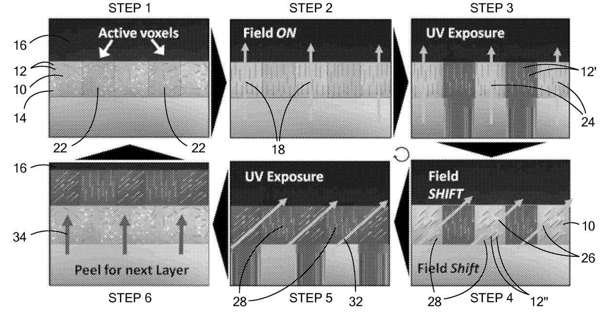
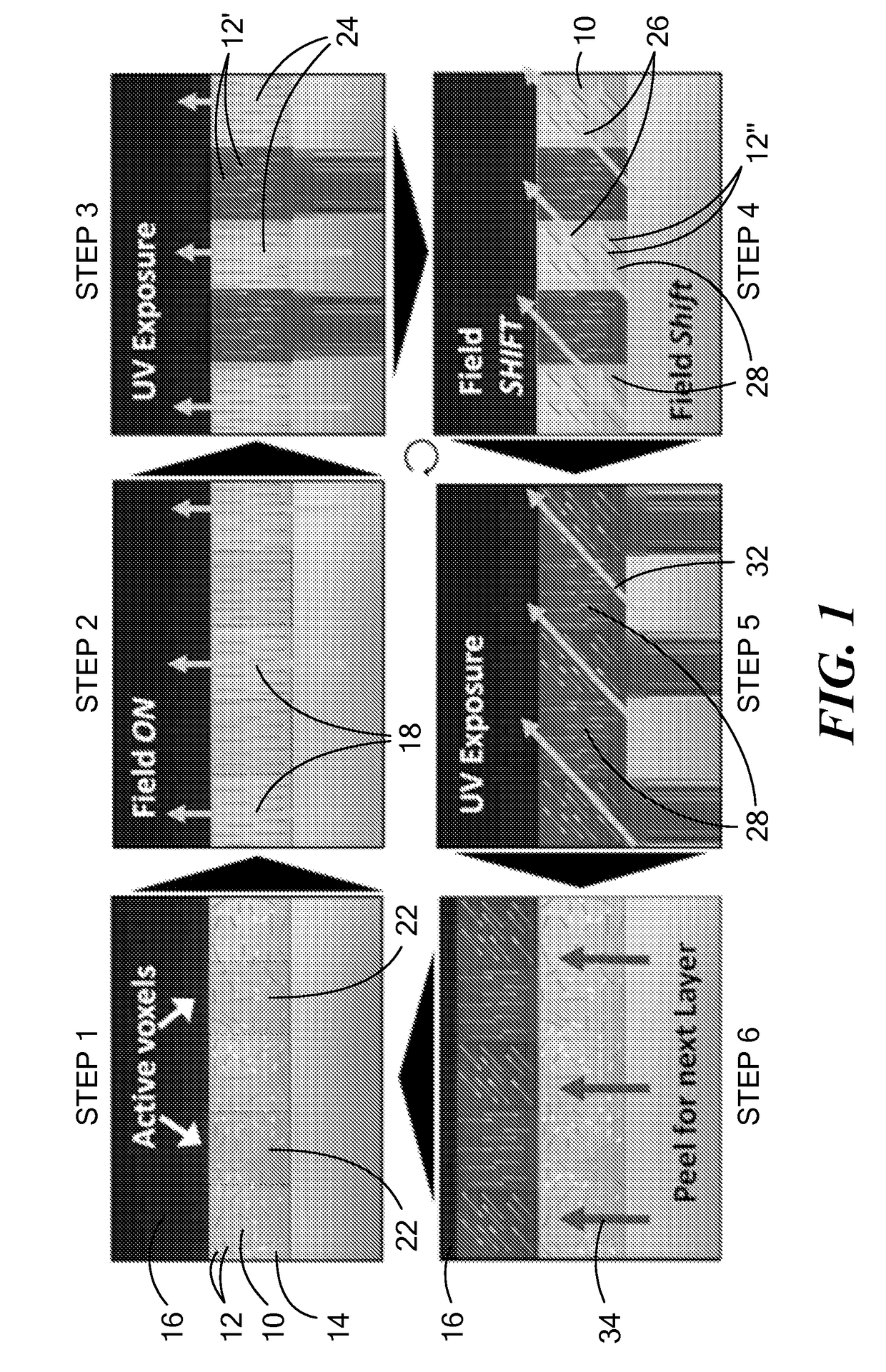
[0168]The feasibility of aligning microscopic particles using magnetic assembly polymer matrices was evaluated with UV curable resins due to their low viscosity and controllable polymerization. Tests were conducted on an N-Scrypt 3Dn table top series modified with a 365 nm light source. A permanent magnet was employed to apply a magnetic field in different directions. Two different fillers were investigated: calcium phosphate rods and alumina (Al2O3) platelets. The resin system employed was alkoxylated pentaerythritol tetraacrylate (Sartomer) with 1 wt % Irgacure 184 (Ciba, Transparent photoinitiator), ˜1% volume Al2O3 platelets or calcium phosphate rods. Samples were made using both a stereolithography (SLA) technique by aligning particles in a container filled with resin and a technique of aligning particles while printing with a micro-nozzle.

[0169]Particles aligned in the bulk resin container were allowed 5 minutes to align in the magnetic field before polymerization. For the pri...

examples 2-4

[0172]Magnetically responsive reinforcing particles were prepared as follows: Alumina (Al2O3) platelets (obtained from Allusion) were electrostatically coated with approximately 5% surface coverage superparamagnetic iron oxide (Fe3O4) nanoparticles (EMG 705, obtained from Ferrotec). 10 grams of alumina powder was added to 200 mL of deionized water and stirred vigorously. 375 μL of EMG 705 was then dispersed in 60 mL of deionized water and slowly added to the stirring mixture of particles. After allowing to mix overnight, the particle mixture was filtered and then dried.

[0173]The resin was a polymer blend consisting of isobornyl acrylate (IBOA, from Sigma) and an aliphatic urethane diacrylate (Ebecryl 230, from Allnex). The resin solution consisted of two photoinitiators, 1-hydroxycyclohexyl phenyl ketone (99%, Sigma) and phenylbis(2,4,6-trimethyl-benzoyl)phosphine oxide (97%, Sigma); at 3% and 1.5% wt., respectively. Once the resin was thoroughly mixed, selected amounts of magnetic ...

example 5

[0181]An example of controlling optical properties is illustrated in FIG. 21. A simple checkered pattern and an image of the Statue of Liberty were fabricated within a solid composite block of a urethane / acrylate copolymer directionally reinforced with alumina microplatelets. In the checkered pattern, the reinforcement angles in each square alternate between 0° and 90°. The orientation of the alumina microparticles results in an optical change to the composite surface. In-plane reinforcement scatters more light and appears whiter; out-of-plane reinforcement absorbs more light and appears darker. The process to produce the checkered pattern took a net 2 minutes to product a 2″ by 3″ composite layer. SEM analysis of the reinforcement microstructure revealed high levels of microparticle alignment in the final composite.


PUM

PropertyMeasurementUnit
thicknessaaaaaaaaaa
aspect ratioaaaaaaaaaa
wavelengthaaaaaaaaaa

Abstract

A method and apparatus for producing a composite part are provided to enable composite parts to be assembled with precise control over the orientation and spatial distribution of reinforcing or other particles within a matrix material. The method and apparatus use magnetic fields applied during various additive manufacturing processes to achieve complex particles orientations within each layer of the part. The composite parts can achieve enhanced properties, including mechanical, thermal, electrical and optical properties.

Description

CROSS REFERENCE TO RELATED APPLICATIONS[0001]This application claims priority under 35 §119(e) of U.S. Provisional Application No. 62 / 008,914 filed on Jun. 6, 2014, entitled “Method for the Production of Discontinuous Fiber Architectures in Additive Manufacturing Processes With Magnetic Fields”, the disclosure of which is hereby incorporated by reference.STATEMENT REGARDING FEDERALLY SPONSORED RESEARCH OR DEVELOPMENT[0002]N / ABACKGROUND[0003]Additive manufacturing (sometimes termed 3D printing) is used to fabricate complex three-dimensional structures out of a variety of materials, such as polymers, metals, and ceramics, at levels of resolution down to tens of microns. Load-bearing mechanical structures from gears to functional fuel nozzles for jet engines have been produced by these techniques.[0004]The printing of polymers has been accomplished mainly by extrusion-based direct-write methods for thermoplastics and stereolithography (SLA) based photo-polymerization for both thermopla...

Claims


Application Information

Patent Timeline
Patent Type & Authority Applications(United States)
IPC IPC(8): B29C67/00B33Y10/00B29C71/00B33Y80/00B33Y70/00H01F41/16B33Y30/00
CPCB29C67/0081H01F41/16B33Y10/00B33Y30/00B33Y80/00B29K2105/162B29C67/0088B29C71/0072B29K2505/12B29K2995/0008B33Y70/00B29C70/62B22F2999/00B29C64/124B29C64/165B29C64/393Y02P10/25B22F10/18B22F12/44B22F10/28B22F10/38B22F12/41B22F10/12B33Y70/10B22F2202/05B22F1/056B22F10/10B22F1/0547B29C64/386
Inventor ERB, RANDALLMARTIN, JOSHUA J.
Owner NORTHEASTERN UNIV
Why Eureka
Try Eureka