Analyte sensor

an analyte sensor and sensor electrode technology, applied in the field of sensors, can solve the problems of difficult to get pre- and type 2 diabetic patients to embrace monitoring of their blood sugar, difficult to place transcutaneously with the sensor electrodes in direct contact with patient blood or other body fluids, and set presents some challenges to users, so as to prevent premature actuation, prevent premature release of medical devices, and improve stability

Active Publication Date: 2020-09-08
MEDTRONIC MIMIMED INC
View PDF93 Cites 12 Cited by
  • Summary
  • Abstract
  • Description
  • Claims
  • Application Information

AI Technical Summary

Benefits of technology

[0033]The striker may have resilient snap arms engaging a perimeter of the medical device to releasably hold the medical device in the striker. The releasability of the medical device enables the apparatus to be lifted off the skin leaving the medical device in place. To help prevent premature release of the medical device, the frame has ribs, which contact the arms when the striker is in the first position. This increases the force needed to release the medical device from the striker, before the firing. The ribs may be fixed on the frame and extend longitudinally into the striker, touching the snap arms only when the striker is in the first position, increasing their stiffness and or flexing length. The medical device may be rectangular, possibly with rounded corners and be held in the striker by four of said snap arms, one acting on each corner.

Problems solved by technology

It is often difficult to get pre- and type 2 diabetic patients to embrace monitoring of their blood sugar on a regular basis.
Such thin film sensors hold significant promise in patient monitoring applications, but unfortunately have been difficult to place transcutaneously with the sensor electrodes in direct contact with patient blood or other body fluid.
Because it is necessary to regularly replace the sensors sold with or to be used with these sets, these sets present some challenges to the user.
The insertion process is often long and complex.
After connecting the transmitter, it is common for a user to have to wait over an hour before the sensor starts giving readings, resulting in a break of the monitoring process.
Because the mounting base may be sold separately, it is possible to attach incompatible components together, which can compromise the sensor data.

Method used


Image

  • Analyte sensor
  • Analyte sensor
  • Analyte sensor

Examples


Embodiment Construction

[0079]The following description and the drawings illustrate specific embodiments sufficiently to enable those skilled in the art to practice the system and method described. Other embodiments may incorporate structural, logical, process and other changes. Examples merely typify possible variations. Individual elements and functions are generally optional unless explicitly required, and the sequence of operations may vary. Portions and features of some embodiments may be included in, or substituted for, those of others.

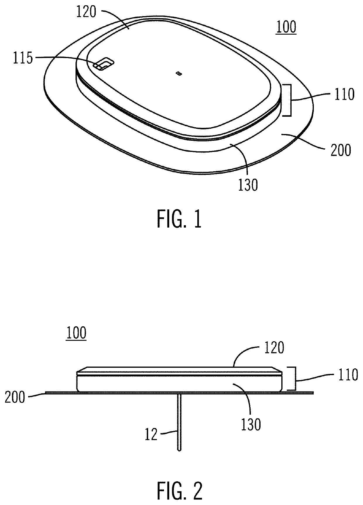
[0080]As shown in the exemplary drawings, an improved sensing device is provided for monitoring a body characteristic of the body. Also provided is an improved structure of the connections between the various components of the sensing device. One example body characteristic is the blood glucose level of the body. As shown in FIG. 1, a configuration of a sensing device 100 includes a housing 110 including an upper housing 120 with an upper major wall inside the upper ho...


PUM


Abstract

A simple, disposable sensing device for sensing an analyte is housed in a single case. The sensing device can transmit sensor data to monitoring device(s). The sensing device includes: a case having a lower major wall adapted to be mounted against a patient's skin, and an upper opposing major wall; a sensor extending from the case and having a distal end sensitive to the analyte to produce an electrical signal, and a proximal end within the case having electrical contacts; a printed circuit board assembly within the case supported by one of the major walls to receive the electrical signal via the electrical contacts; and an elastomeric pad disposed in the case and biased by the other major wall to urge the proximal end of the sensor into contact with the printed circuit board assembly and maintain an electrical connection between the electrical contacts and the printed circuit board assembly.

Description

CROSS-REFERENCE TO RELATED APPLICATIONS[0001]The present disclosure claims priority to and the benefit of U.S. Provisional Patent Application Ser. No. 62 / 320,290 filed on Apr. 8, 2016, U.S. Provisional Application Ser. No. 62 / 344,847 filed on Jun. 2, 2016, U.S. Provisional Patent Application Ser. No. 62 / 344,852 filed on Jun. 2, 2016, U.S. Provisional Patent Application Ser. No. 62 / 402,676 filed on Sep. 30, 2016, U.S. Provisional Patent Application Ser. No. 62 / 460,710 filed on Feb. 17, 2017, U.S. Non Provisional patent application Ser. No. 15 / 357,885 filed on Nov. 21, 2016, U.S. Non Provisional patent application Ser. No. 15 / 357,925 filed on Nov. 21, 2016, U.S. Non Provisional patent application Ser. No. 15 / 357,952, filed on Nov. 21, 2016, the contents of which are incorporated herein by reference in their entirety.BACKGROUND OF THE DISCLOSUREField of the Disclosure[0002]The present disclosure generally relates to a sensor for monitoring a body characteristic of the body, such as glu...

Claims


Application Information

Patent Timeline
Patent Type & Authority Patents(United States)
IPC IPC(8): A61B5/00A61B5/145A61B5/1486A61B17/34A61B5/1473
CPCA61B5/14532A61B5/6833A61B5/1473A61B5/14865A61B5/742A61B5/14503A61B17/3468A61B5/746A61B5/6849A61B2560/0468A61B2560/0406A61B2562/227A61B2560/0219A61B2562/125A61B2560/0412A61B2560/063A61B2562/166A61B2560/045
Inventor ANTONIO, DAVID C.LARSON, ERIC ALLANRUELAS, JOSE J.RANAUTA, SUKHJEET S.
Owner MEDTRONIC MIMIMED INC
Why Eureka
Try Eureka