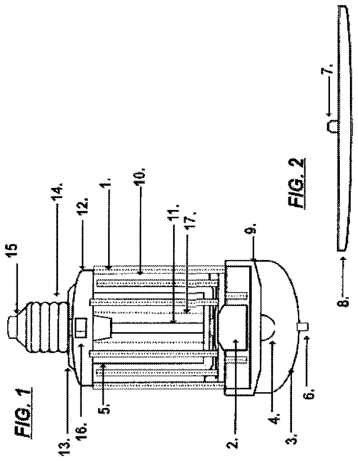
Electronic insect-control system

a technology of electronic insect control and insect trap, which is applied in the direction of insect catchers and killers, light source combinations, lighting and heating devices, etc., can solve problems such as source of discomfor

Active Publication Date: 2021-07-20
BILLINGSLEY JR FRANK
View PDF6 Cites 1 Cited by
  • Summary
  • Abstract
  • Description
  • Claims
  • Application Information

AI Technical Summary

Problems solved by technology

Traditionally light sources such as light bulbs attract insects, e.g., mosquitoes, flies, etc., and therefore are a source of discomfort, particularly when used in outdoor settings in certain climates.

Method used


Image

  • Electronic insect-control system

Examples


Embodiment Construction

[0021]It will be readily understood that the components of the embodiments, as generally described and illustrated in the figures herein, may be arranged and designed in a wide variety of ways in addition to the examples described herein. The detailed description uses examples, represented in the figures, but these examples are not intended to limit the scope of the claims.

[0022]Reference throughout this specification to “embodiment(s)” (or the like) means that a particular described feature or characteristic is included in that example. This particular feature or characteristic may or may not be claimed. This particular feature may or may not be relevant to other embodiments. For the purpose of this detailed description, each example might be separable from or combined with another example, i.e., one example is not necessarily relevant to other examples.

[0023]Therefore, the described features or characteristics of the examples generally may be combined in any suitable manner, altho...


PUM

PropertyMeasurementUnit
sizeaaaaaaaaaa
voltageaaaaaaaaaa
powersaaaaaaaaaa

Abstract

One embodiment provides a system, including: a first end that screws into a light bulb socket; an internal light source; an electric insect control mechanism disposed around and proximate to the internal light source; and a visible light source disposed at an opposite end with respect to the first end. Other embodiments are described and claimed.

Description

[0001]This application claims priority to U.S. Provisional Patent Application Ser. No. 62 / 493,271, entitled “Bug zapper light bulb,” and filed on Jun. 27, 2016, the contents of which are fully incorporated by reference as if set forth in their entirety herein.FIELD[0002]The subject matter described herein relates to an insect-control device and specifically relates to a combined lightbulb and electronic insect-control system.BACKGROUND[0003]Traditionally light sources such as light bulbs attract insects, e.g., mosquitoes, flies, etc., and therefore are a source of discomfort, particularly when used in outdoor settings in certain climates. Conventionally electrical mechanisms for killing insects (electronic insect-control systems or “bug zappers”) have been constructed as stand-alone-units that operate by being plugged into a commercial power source (i.e., use a cord that inserts into a two or three-pronged wall plug). These units typically include an internal light source of some ty...

Claims


Application Information

Patent Timeline
Patent Type & Authority Patents(United States)
IPC IPC(8): A01M1/22A01M1/04F21K9/235F21K9/238F21K9/232F21V3/06H05B47/19F21Y115/10F21Y113/20
CPCA01M1/223A01M1/04F21K9/232F21K9/235F21K9/238F21V3/061H05B47/19F21Y2113/20F21Y2115/10H05B47/195
Inventor BILLINGSLEY, JR., FRANK
Owner BILLINGSLEY JR FRANK
Why Eureka
Try Eureka