External fixator system

a fixator and external technology, applied in the field of external fixation frames, can solve the problems of static foot fixation products on the market, difficulty for patients, and limited patient access to devices,

Active Publication Date: 2021-10-12
STRYKER EURO OPERATIONS HLDG LLC
View PDF351 Cites 0 Cited by
  • Summary
  • Abstract
  • Description
  • Claims
  • Application Information

AI Technical Summary

Problems solved by technology

As the position adjustments of the components are made where the nuts are secured, it can be difficult for the patient, for example, to make the required daily adjustments with consideration of maintaining stable fixation.
The devices generally offer limited access for the patient.
For example, existing foot fixation products on the market are static and do not allow for adjustment and pivoting.
This lack of flexibility and motion restricts the motion of the foot and ankle and the external fixation frame during deformity correction, making the process more difficult for the physician and the patient and potentially preventing an optimal clinical outcome.

Method used


Image

  • External fixator system
  • External fixator system
  • External fixator system

Examples


Embodiment Construction

[0040]As used herein, the term “proximal” means a direction closer to the heart of a patient and the term “distal” means a direction farther away from the heart of a patient. The term “anterior” means towards the front part of the body or the face and the term “posterior” means towards the back of the body. The term “medial” means toward the midline of the body and the term “lateral” means away from the midline of the body.

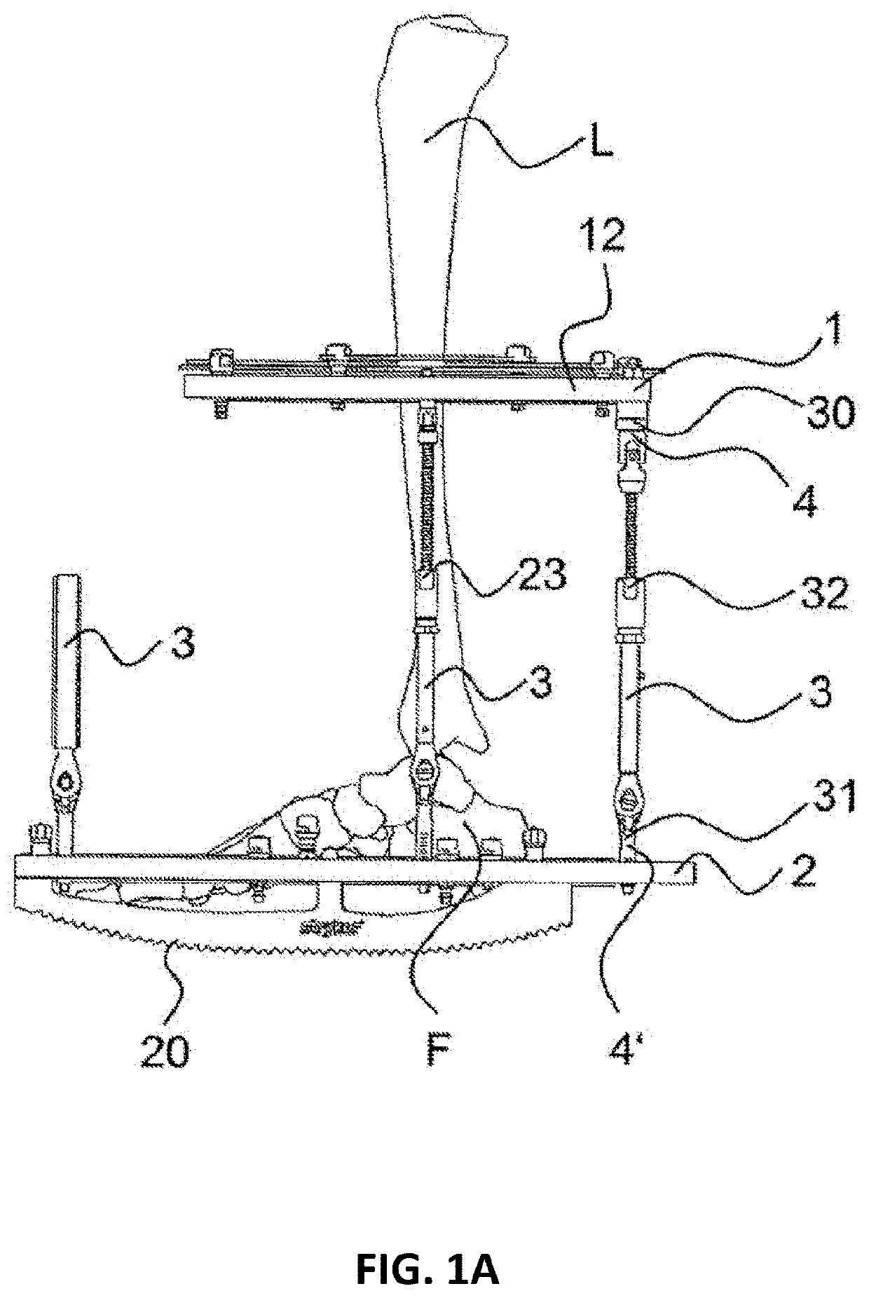
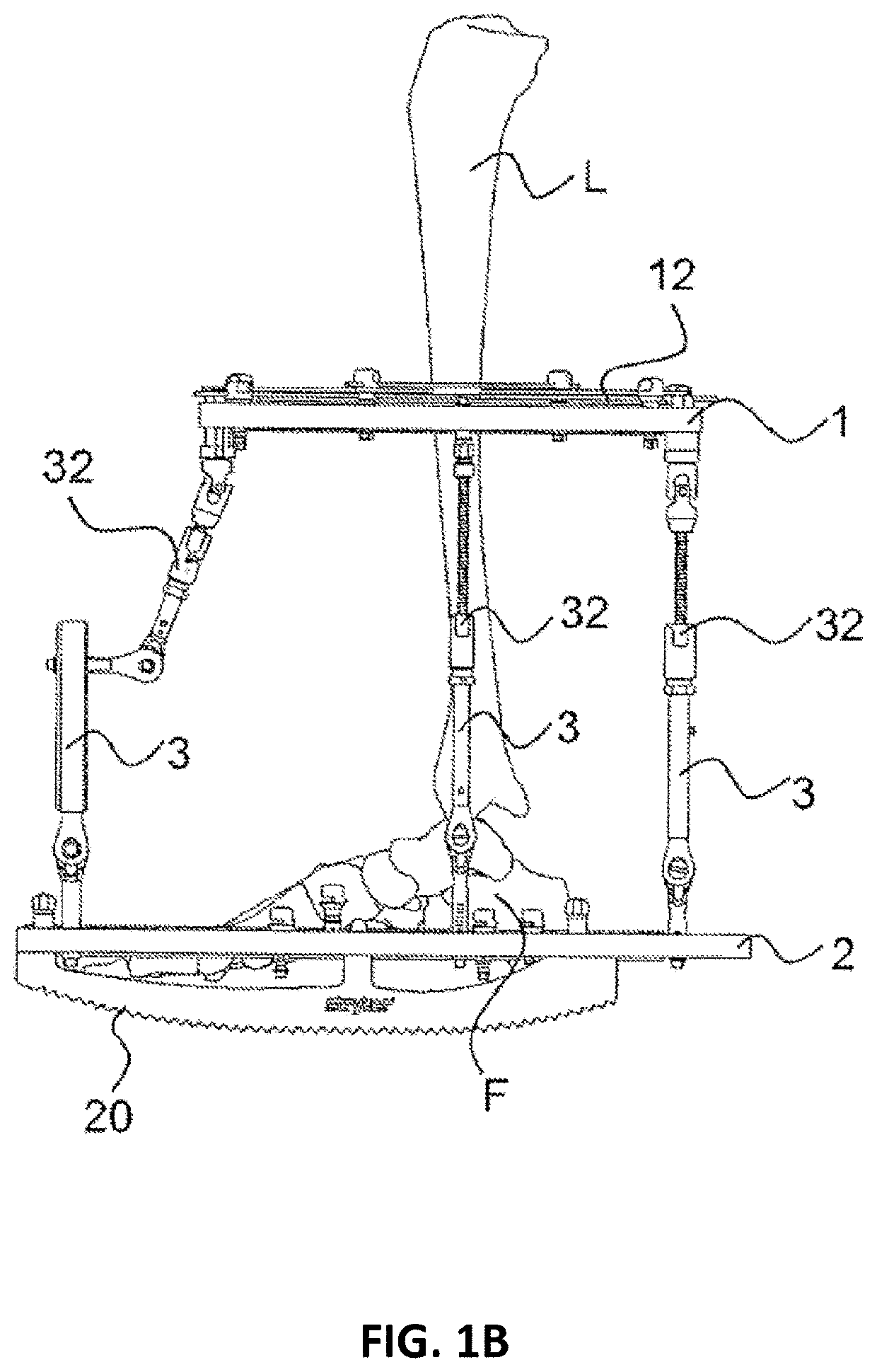
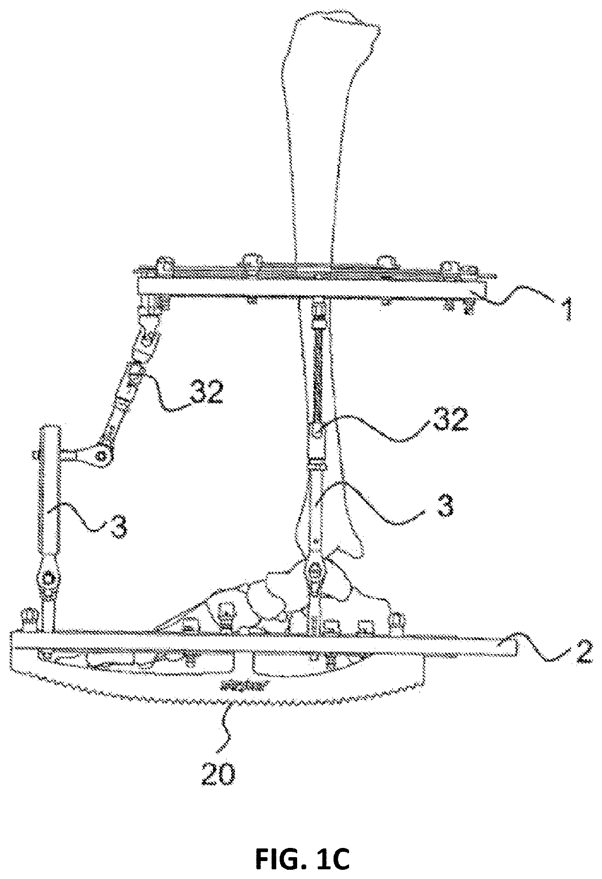
[0041]Referring to FIGS. 1-6, there is shown an embodiment of an external fixator system of the present invention. As shown in those figures, the external fixator system includes first and second fixation plates 1, 2 coupled to first and second bone segments L, F respectively, a plurality of adjustable length struts 3, at least one actuation unit 4, and a plurality of clamping units 4′.

[0042]FIGS. 1A-E show an exemplary embodiment of an external fixator system. The external fixator system comprises at least two fixation plates 1, 2 which are arranged at a distance...


PUM


Abstract

Disclosed herein are external fixation frames for correcting bone deformities. The external fixation frames include a top fixation ring and a bottom fixation ring coupled to one another by at least two struts. A half ring is coupled to bottom fixation ring. The bottom fixation ring is u-shaped. One or more rocker members may be coupled to the bottom fixation ring. The half ring may be hingedly coupled to the bottom fixation ring such that it can rotate with respect to the bottom fixation ring from a first position to a second position.

Description

CROSS-REFERENCE TO RELATED APPLICATIONS[0001]The present application is continuation of U.S. patent application Ser. No. 16 / 108,787, filed Aug. 22, 2018, which is a continuation of U.S. Pat. No. 10,080,585, filed Jun. 28, 2017, which is a continuation of U.S. Pat. No. 9,839,445, filed Apr. 12, 2017, which is a continuation of U.S. Pat. No. 9,730,730, filed May 8, 2015, which is a continuation of U.S. Pat. No. 9,220,533, filed Dec. 9, 2014, which is a continuation of U.S. Pat. No. 8,945,128, filed Mar. 11, 2013, which is a continuation-in-part of U.S. Pat. No. 8,834,467, filed Aug. 9, 2011, which claims priority to European Application No. 10 172 523.2, filed Aug. 11, 2010, and European Application No. 11 176 512.9, filed Aug. 4, 2011. The disclosures of each of the above-referenced applications are hereby incorporated by reference herein.FIELD OF THE INVENTION[0002]The present disclosure relates to an external fixation frame for correcting a bone deformity. More particularly, the pr...

Claims


Application Information

Patent Timeline
Patent Type & Authority Patents(United States)
IPC IPC(8): A61B17/62A61B17/64A61H3/00A61B17/66A61B17/88
CPCA61B17/62A61B17/645A61B17/6425A61B17/66A61H3/00A61B17/8875A61B17/6466
Inventor SINGH, MANOJ KUMARCROZET, YVES STEPHANEBURGHERR, VINZENZ ANDREASDAHL, MARK THOMAS
Owner STRYKER EURO OPERATIONS HLDG LLC
Why Eureka
Try Eureka