Cup holder cleaning tool

a cleaning tool and cup holder technology, applied in the field of cleaning tools, can solve the problems of prone to collecting spills and debris, and some remaining contamination stuck to the side,

Active Publication Date: 2022-01-04
MOHAMMED NASIR
View PDF17 Cites 7 Cited by
  • Summary
  • Abstract
  • Description
  • Claims
  • Application Information

AI Technical Summary

Benefits of technology

[0008]The diameter adjustment mechanism may be locked in position by a locking thumbscrew. The upper enclosure may be made of plastic. The cleaning solution reservoir and the used cleaning solution reservoir may contain cleaning solution and the used cleaning solution respectively and may be capped by the cleaning solution reservoir cap and the used cleaning solution reservoir cap respectively. The cleaning solution supply tube and the used cleaning solution vacuum tube may be adjustable up and down along a first tube travel path. The tube height adjustment mechanism may allow for stabilized motion of the cleaning solution supply tube and the used cleaning solution vacuum tube up and down along a second tube travel path which accommodates and is directly proportional to the first tube travel path.

Problems solved by technology

One other area that is prone to collecting spills and debris is that of the cup holders.
However, no matter how much vacuuming, wiping, and brushing one does, there always seems to be some remaining contamination that remains stuck to the sides due to the tight configuration of the cupholder.

Method used


Image

  • Cup holder cleaning tool
  • Cup holder cleaning tool
  • Cup holder cleaning tool

Examples


Embodiment Construction

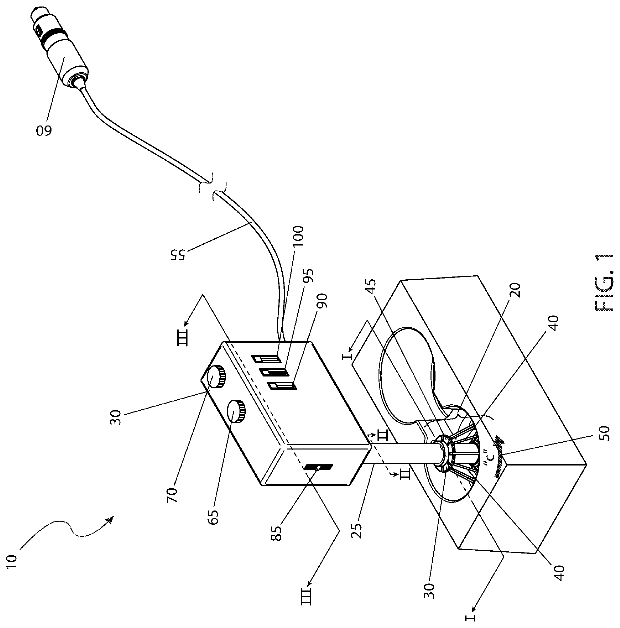
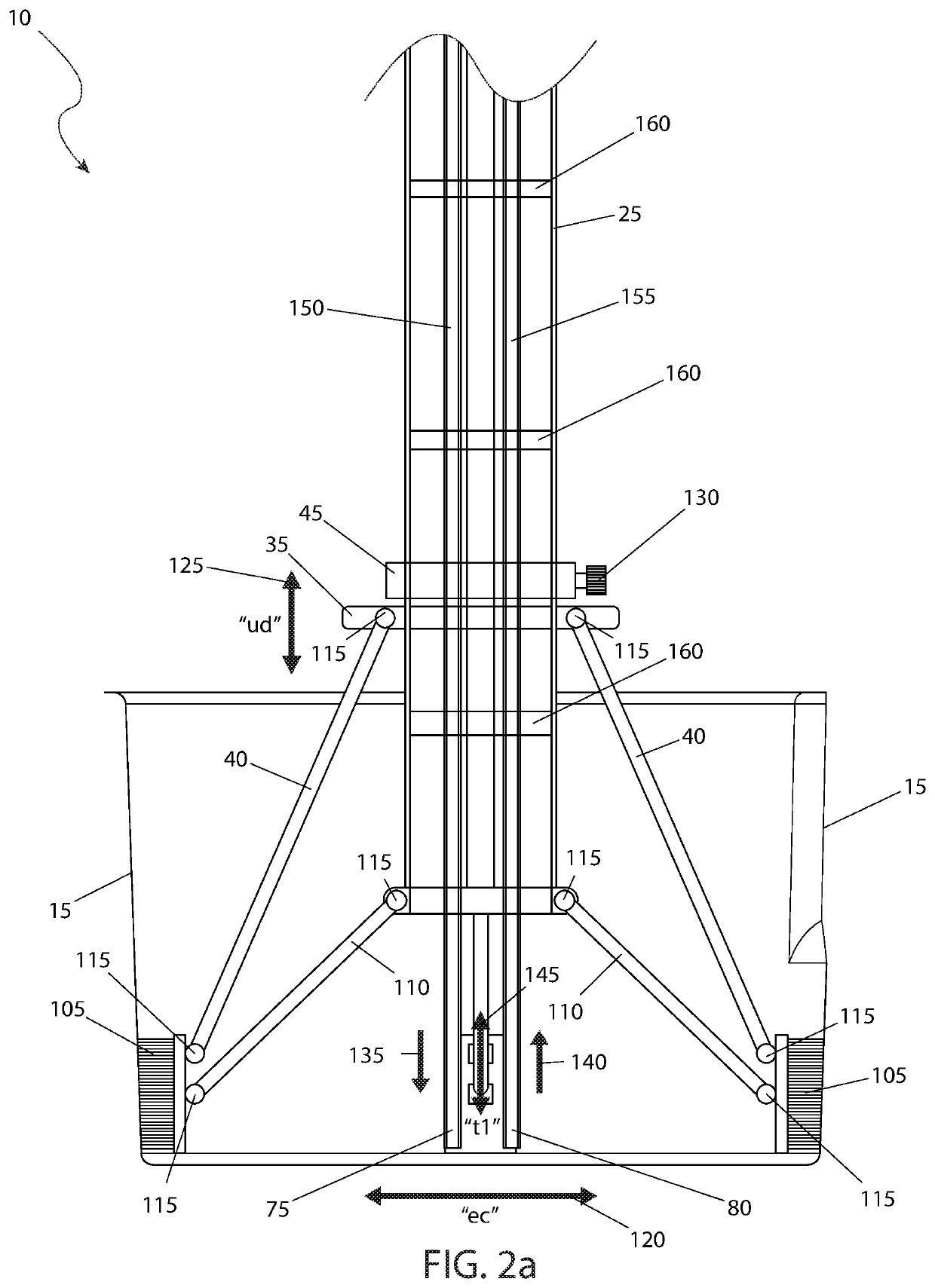
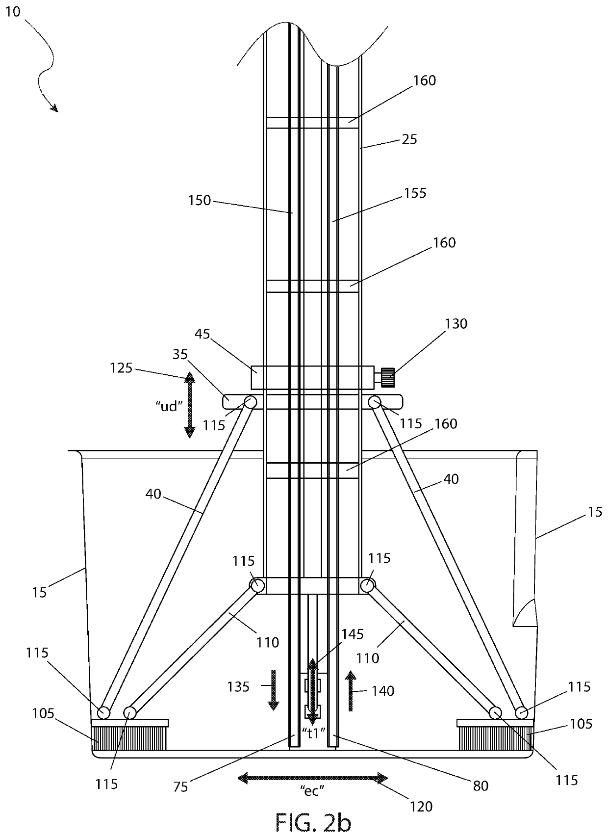
[0065]The best mode for carrying out the invention is presented in terms of its preferred embodiment, herein depicted within FIGS. 1 through 5. However, the invention is not limited to the described embodiment, and a person skilled in the art will appreciate that many other embodiments of the invention are possible without deviating from the basic concept of the invention and that any such work around will also fall under scope of this invention. It is envisioned that other styles and configurations of the present invention can be easily incorporated into the teachings of the present invention, and only one (1) particular configuration shall be shown and described for purposes of clarity and disclosure and not by way of limitation of scope. All of the implementations described below are exemplary implementations provided to enable persons skilled in the art to make or use the embodiments of the disclosure and are not intended to limit the scope of the disclosure, which is defined by...


PUM


Abstract

A cleaning tool utilizes an electrical motor in communication with a power supply secured to a lengthwise adjustable arm secured in turn to a collapsible and foldable cleaning head. The cleaning head comprises a plurality of brush heads perpendicularly secured in a radial array beneath a brush head support plate of the cleaning head. The cleaning tool is particularly suited to clean a cup holder.

Description

RELATED APPLICATIONS[0001]None.FIELD OF THE INVENTION[0002]The present invention relates generally to a cleaning tool and more specifically to a cup holder cleaning tool.BACKGROUND OF THE INVENTION[0003]Among the many chores that we all must face is the task of keeping our cars clean and good-looking. For many Americans, their car is a source of personal pride and keeping it good looking is not just a chore, it is an obsession. This obsession of course includes the interior of the car as well. The upholstery and carpeting must be vacuumed and periodically cleaned to keep it looking its best. Dashes and instrument panels must be wiped down and brushed to remove all traces of dust and dirt. One other area that is prone to collecting spills and debris is that of the cup holders. However, no matter how much vacuuming, wiping, and brushing one does, there always seems to be some remaining contamination that remains stuck to the sides due to the tight configuration of the cupholder. Accor...

Claims


Application Information

Patent Timeline
Patent Type & Authority Patents(United States)
IPC IPC(8): A46B13/04B08B1/04B08B9/087B08B9/08B08B9/093
CPCA46B13/04B08B1/04B08B9/087B08B9/0808B08B9/093B60S3/008A46B5/0058
Inventor MOHAMMED, NASIR
Owner MOHAMMED NASIR
Why Eureka
Try Eureka