Supercharge Your Innovation With Domain-Expert AI Agents!

Multi-port multi-plane valve

a multi-plane, valve technology, applied in the direction of multiple way valves, valve arrangements, engine cooling apparatus, etc., can solve the problems of increasing the overall increasing the number of parts, and increasing the complexity of the valve, so as to reduce the number of parts and reduce the cost.

Active Publication Date: 2022-02-22
ROBERTSHAW CONTROLS CO
View PDF70 Cites 5 Cited by
  • Summary
  • Abstract
  • Description
  • Claims
  • Application Information

AI Technical Summary

Benefits of technology

The present invention provides a multi-port multi-plane valve that has a reduced part count and cost relative to prior designs, and that allows for multi-planar fluid flow and control. The valve includes a housing with multiple ports in different planes. A shell body is rotatably positioned within the housing to provide flow between the different ports. A seal member surrounds the shell body to seal the ports in the same plane from each other. The seal member can seal outwardly against the housing or against the shell body. The valve also includes a plurality of port bodies and a plurality of seal segments. The technical effects of this invention include improved efficiency and control over fluid flow, reduced costs, and improved durability and reliability.

Problems solved by technology

However, such multi-port valves are not without their own drawbacks.
For example, the overall complexity of the valve increases as the number of ports increases.
This can lead to relatively high part count assemblies.
Further, this complexity in construction also results in a more complex manufacturing process for making the valve.
Such welded up assemblies increase the number of potential leak paths of the valve.
These multiple seals also lead to an increase in overall cost and complexity of the multi-port valve.
Unfortunately, the use of such external plumbing greatly increases the required volume or footprint of the overall fluid control system, and can create problems necessitating re-routing and re-locating of other components in its or other systems that need to occupy that volume.

Method used


Image

  • Multi-port multi-plane valve
  • Multi-port multi-plane valve
  • Multi-port multi-plane valve

Examples


Embodiment Construction

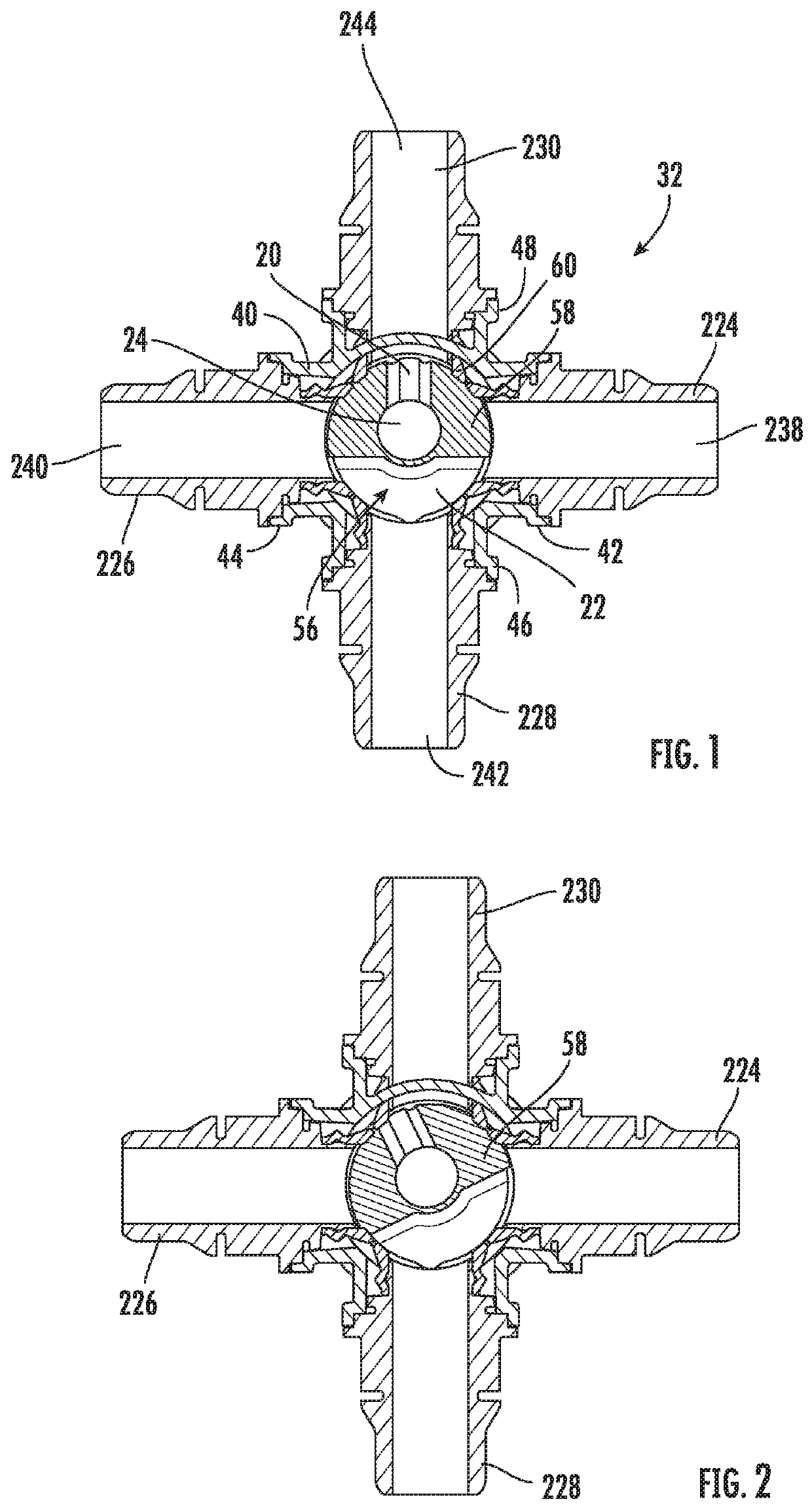
[0038]Turning now to the figures, as will be understood from the following, embodiments of a multi-port multi-plane valve assembly and its associated multi-port multi-plane valve are described herein. The multi-port multi-plane valve advantageously overcomes existing problems in the art by presenting an overall construction with a reduced part count, a reduced number of potential leak paths, a reduction in overall assembly time and cost, and reduced external plumbing to provide fluid flow and control in multiple planes.

[0039]As discussed in the above identified co-pending U.S. patent application Ser. No. 15 / 945,173 (Publication No. 2018 / 0292016, “Multi-port valve” by Joe Ledvora et al.), filed Apr. 4, 2018, the teachings and disclosure of which is hereby incorporated in its entirety by reference thereto, multi-port valve assemblies typically, as here, include an actuator (not shown herein) mounted to the multi-port valve. The actuator is responsible for actuating a valve member (i.e...


PUM


Abstract

Embodiments of a multi-port multi-plane valve are provided. The multi-port multi-plane valve includes a housing which defines an internal cavity. The housing further includes a plurality of ports in which each port lies within one of two planes that are normal to each other. Each of the plurality of ports is in communication with the internal cavity. A shell body is rotatably disposed within the internal cavity and provides selectable fluid communications between the ports. A seal member is also provided which has a plurality of openings and surrounds the shell body. At least one flow enhancer channel may be included to reduce the pressure drop occurring on one side of the valve when controlling flow paths on the other side of the valve.

Description

CROSS-REFERENCE TO RELATED PATENT APPLICATION[0001]This patent application claims the benefit of U.S. Provisional Patent Application No. 62 / 782,155, filed Dec. 19, 2018, the entire teachings and disclosure of which are incorporated herein by reference thereto.FIELD OF THE INVENTION[0002]This invention generally relates to multi-port valves, and more particularly to multi-port valves having multiple inlet and outlet ports to control flow in different planes.BACKGROUND OF THE INVENTION[0003]Multi-port valves are used in a variety of industries and applications. Such valves include one or more inlet ports and one or more outlet ports. A valve member disposed within a housing of the valve is responsible for governing the flow between the various ports. A portion of the valve member, e.g. a valve stem, protrudes from the housing and is acted upon by an actuator attached to the multi-port valve. As result, the actuator governs the position of the valve member within the housing, which in ...

Claims


Application Information

Patent Timeline
Patent Type & Authority Patents(United States)
IPC IPC(8): F16K11/085F16K5/04
CPCF16K11/0856F16K5/0471F16K11/085F01P2007/146F01P7/16
Inventor LEDVORA, JOSEPHDAVERN, THOMAS J.PEARSON, JAMES E.
Owner ROBERTSHAW CONTROLS CO
Features
  • R&D
  • Intellectual Property
  • Life Sciences
  • Materials
  • Tech Scout
  • Unparalleled Data Quality
  • Higher Quality Content
  • 60% Fewer Hallucinations
Learn More