
System and method for generating computerized floor plans

a computerized and floor plan technology, applied in the field of system and method for generating computerized floor plans, can solve the problems of time-consuming and labor-intensive manual measurement of room features, inability to be reliable, and difficult for users to utilize, so as to achieve quick and convenient measurement, high accuracy, and quick and convenient delineation of wall corner features.

Active Publication Date: 2022-04-26
XACTWARE SOLUTIONS
View PDF70 Cites 4 Cited by
  • Summary
  • Abstract
  • Description
  • Claims
  • Application Information

AI Technical Summary

Benefits of technology

The present invention is a system and method for creating computerized floor plans using a mobile computing device, such as a smartphone or tablet, and an interior modeling software engine. The system utilizes a gyroscope and camera to quickly and conveniently measure interior building features and create accurate floor plans without the need to stay in a single location. The system provides a user-friendly interface to delineate wall corner features and calculate wall dimensions, resulting in a detailed floor plan. The floor plan can be displayed on the mobile device or transmitted to a remote computer system, such as a building estimation server. The technical effect of this invention is to make floor planning faster, more convenient, and with higher accuracy.

Problems solved by technology

Moreover, manually measuring room-features is time-consuming and prone to inaccurate results.
However, such systems may not always be reliable, and they can be difficult for a user to utilize.
Further, some systems require a user to remain in one place while measuring all the dimensions of an entire room, which is inconvenient and can lead to incorrect results.

Method used


Image

  • System and method for generating computerized floor plans
  • System and method for generating computerized floor plans
  • System and method for generating computerized floor plans

Examples


Embodiment Construction

[0024]The present disclosure relates to a system and method for generating computerized floor plans, as discussed in detail below in connection with FIGS. 1-20.

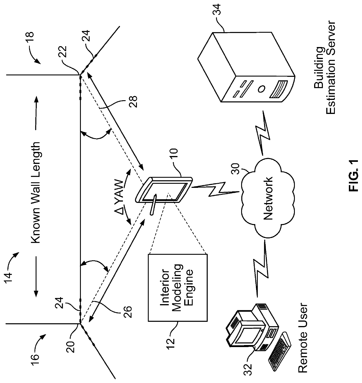
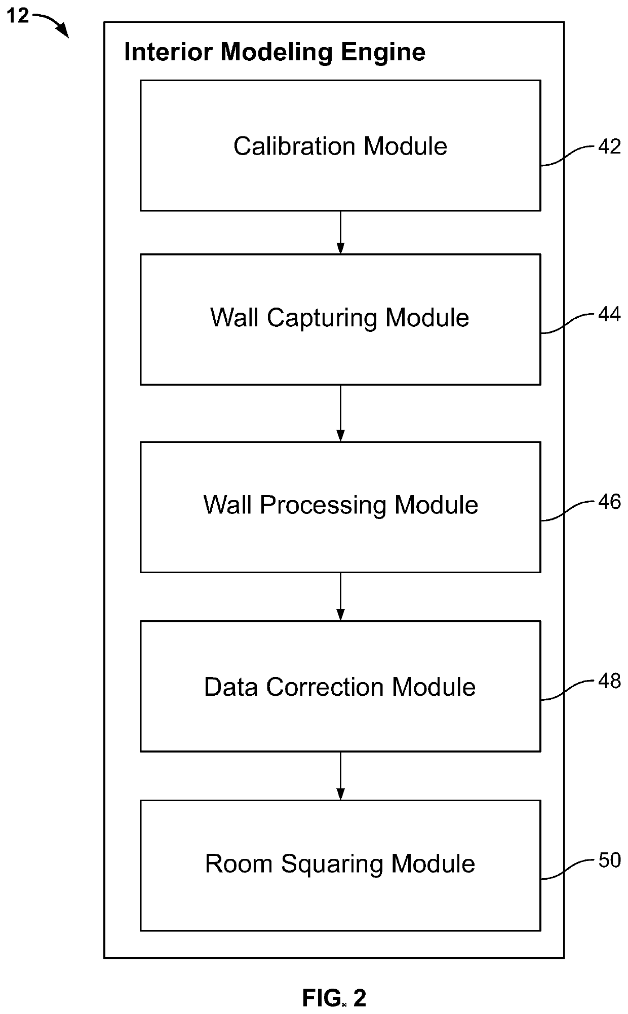
[0025]FIG. 1 is a diagram showing a general overview of the floor plan generating system. The system comprises a mobile computing device 10 that includes an interior modeling engine 12, a display screen, and a local memory. While the interior modeling engine 12 is described herein as a single engine, it should be understood that the interior modeling engine 12 could be made up of any number of engines while remaining within the scope of the present disclosure. The mobile computing device 10 could be in a communicative relationship with a remote user computing device 32 and / or with a building estimation server 34 via a network 30. The mobile computing device 10 could be utilized within an interior space of a building, such as a room. It should be well understood that the term “indoor space” is used to mean any kind of space, i...


PUM


Abstract

A system and method for generating computerized floor plans is provided. The system comprises a mobile computing device, such as a smart cellular telephone, a tablet computer, etc. having an internal digital gyroscope and camera, and an interior modeling software engine interacts with the gyroscope and camera to allow a user to quickly and conveniently take measurements of interior building features, and to create computerized floor plans of such features from any location within a space, without requiring the user to stay in a single location while taking the measurements. The system presents the user with a graphical user interface that allows a user to quickly and conveniently delineate wall corner features using a reticle displayed within the user interface. As corners are identified, the system processes the corner information and information from the gyroscope to calculate wall features and creates a floor plan of the space with high accuracy.

Description

RELATED APPLICATIONS[0001]This application claims the benefit of U.S. Provisional Application Ser. No. 61 / 938,507 filed on Feb. 11, 2014, the entire disclosure of which is expressly incorporated herein by reference.BACKGROUND OF INVENTIONField of the Disclosure[0002]The present disclosure relates generally to a system and method for generating computerized floor plans using a mobile computing device. More specifically, the present disclosure relates to a system and method for measuring interior features of a space (such as wall lengths, corners, etc.), processing the measured parameters to create a computerized (digital) floor plan of the space, and outputting the computerized floor plan.Related Art[0003]Floor plans are useful in a vast number of fields, such as construction and / or insurance estimation, interior decorating, real estate valuation, and other applications. Floor plans are not always available, and when they are, they sometimes lack accuracy. Moreover, manually measurin...

Claims


Application Information

Patent Timeline
Patent Type & Authority Patents(United States)
IPC IPC(8): G06F30/13
CPCG06F30/13
Inventor CHILDS, BRADLEY MCKAYTAYLOR, JEFFREY C.LEWIS, JEFFERY D.REED, COREY
Owner XACTWARE SOLUTIONS
Learn More