Supercharge Your Innovation With Domain-Expert AI Agents!

Method for mounting and/or removing components of a turbine having a turbine casing, adapter and system for use in the method as well as use of an adapter

a technology of turbine casing and components, which is applied in the direction of engines, machines/engines, mechanical equipment, etc., can solve the problems of not insignificant weight, manual mounting and/or removal, and the component problem is not significan

Active Publication Date: 2022-06-14
SIEMENS AG
View PDF20 Cites 0 Cited by
  • Summary
  • Abstract
  • Description
  • Claims
  • Application Information

AI Technical Summary

Benefits of technology

The invention provides a way to fasten a crane to a turbine casing, which has several benefits. Firstly, it allows the crane to be positioned close to the mounting and dismounting position, which simplifies the process. Secondly, it eliminates the need for heavy counterweights at the feet of the crane, as the turbine itself serves as the necessary counterweight for transporting heavy components. In one configuration, the crane is fastened to the turbine casing using a through-passage bore present in the casing. This eliminates the need for casing modification and reduces the cost. The crane can be easily connected to a mobile crane by using an adapter with matching bores. The adapters can be used with different configurations of turbine casings by simply designing an adapter for each type of casing. To overcome space limitations, an adapter with recesses at a suitable position can be used for temporary fixing of the crane. The recesses can be customized for the specific casing configuration, including the number, size, and position of non-removable elements. Overall, the invention provides a simple and cost-effective solution for fastening a crane to a turbine casing, allowing for easy positioning and transportation of heavy components.

Problems solved by technology

The operations of mounting and / or removing turbine components, which can be for example the blades of the turbine, gives rise to the problem of the components in some cases having a not insignificant weight and having to be mounted and / or removed in a disadvantageous working position.
Manual mounting and / or removal is problematic on account of the weight and the disadvantageous working position.

Method used


Image

  • Method for mounting and/or removing components of a turbine having a turbine casing, adapter and system for use in the method as well as use of an adapter
  • Method for mounting and/or removing components of a turbine having a turbine casing, adapter and system for use in the method as well as use of an adapter
  • Method for mounting and/or removing components of a turbine having a turbine casing, adapter and system for use in the method as well as use of an adapter

Examples


Embodiment Construction

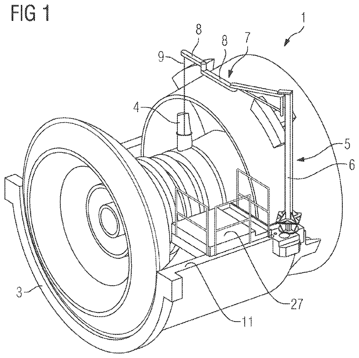
[0046]FIG. 1 shows a perspective view of a portion of a turbine 1. The turbine 1 comprises, in a manner known per se, a rotor 2 and a two-part turbine casing, of which only the lower casing half 3 can be seen in FIG. 1, since the upper casing half has been removed.

[0047]The blades 4 are to be removed from the rotor 2 of the turbine 1, and in the exemplary embodiment illustrated this takes place with implementation of one embodiment of the method according to embodiments of the invention.

[0048]For this purpose, in a first step, a mobile crane 5 has been fastened on the turbine casing. FIG. 1 shows the crane 5 already fastened on the casing.

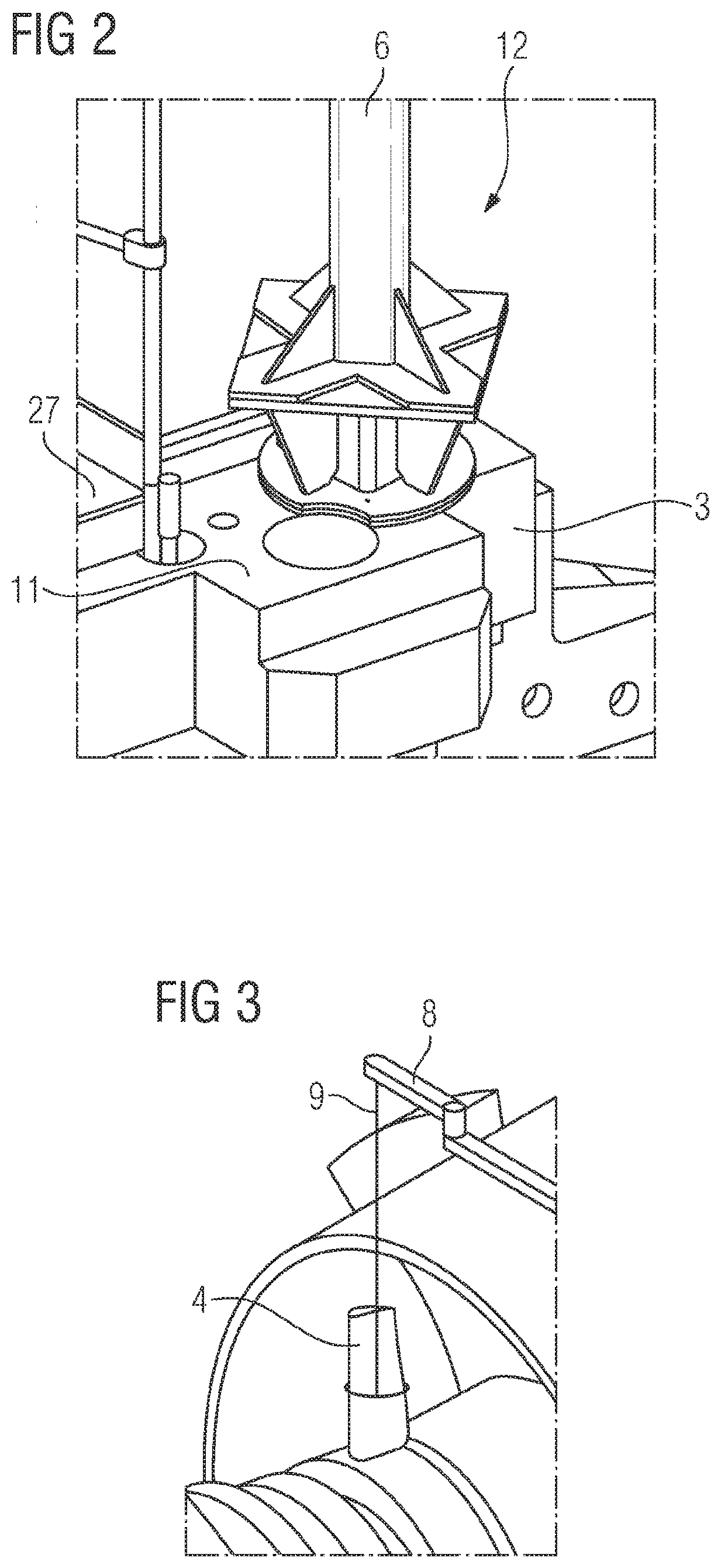
[0049]The mobile crane 5 comprises a tower 6 and a jib 7, which is fastened on the tower in an articulated manner. In order to provide greater deflection-related flexibility, the jib 7 is subdivided into three segments 8, which in turn are connected to one another in an articulated manner. A cable 9 is fastened at the free end of the jib 7, the oth...


PUM


Abstract

A method for mounting and / or dismantling turbine components is provided. According to this method, a crane is fastened to a turbine casing half in the area of the joint, and at least one component such as for example a turbine blade is brought into its mounted position and / or is removed from its mounted position by means of the crane. For this purpose, the crane has a tower with a multiple section jib having a plurality of segments, thereby allowing the components to be positioned accurately for mounting / dismantling. The mobile crane is connected to the turbine casing half by means of an adapter. The adapter has a fastening pin which is held in place by means of an existing through-bore in the turbine casing half. For the purpose of mounting the mobile crane, the adapter has a baseplate. For rotational locking of the crane, a securing element is provided.

Description

CROSS-REFERENCE TO RELATED APPLICATIONS[0001]This application claims priority to PCT Application No. PCT / EP2018 / 050323, having a filing date of Jan. 8, 2018, which is based on German Application No. 10 2017 200 367.7, having a filing date of Jan. 11, 2017, the entire contents both of which are hereby incorporated by reference.FIELD OF TECHNOLOGY[0002]The following relates to a method for mounting and / or removing components of a turbine having a turbine casing. The following also relates to an adapter and a system for use in the method. Finally, the following relates to the use of an adapter.BACKGROUND[0003]The operations of mounting and / or removing turbine components, which can be for example the blades of the turbine, gives rise to the problem of the components in some cases having a not insignificant weight and having to be mounted and / or removed in a disadvantageous working position. In the case of some types of turbine, it is for example necessary for the blades to be removed in...

Claims


Application Information

Patent Timeline
Patent Type & Authority Patents(United States)
IPC IPC(8): F01D25/28
CPCF01D25/285F05D2230/68F05D2230/60F05D2230/70F05D2260/31
Inventor CIMEN, SEZGINRUNGE, BENJAMINMEYER, THOMAS
Owner SIEMENS AG
Features
  • R&D
  • Intellectual Property
  • Life Sciences
  • Materials
  • Tech Scout
  • Unparalleled Data Quality
  • Higher Quality Content
  • 60% Fewer Hallucinations
Learn More