Fe-based soft magnetic alloy, manufacturing method therefor, and magnetic parts using Fe-based soft magnetic alloy

a soft magnetic alloy and soft magnetic technology, applied in the direction of transformer/inductance magnetic core, core/yokes, magnetic bodies, etc., can solve the problems of difficult control of crystal size, limited material approach, and lowered saturated magnetic flux density of alloy, and achieve excellent high frequency characteristics, high saturated magnetic flux density, and low coercivity.

Active Publication Date: 2022-06-28
AMOGREENTECH CO LTD +1
View PDF15 Cites 0 Cited by
  • Summary
  • Abstract
  • Description
  • Claims
  • Application Information

AI Technical Summary

Benefits of technology

[0010]The present invention has been devised in consideration of the above-described points, and an object thereof is to provide an Fe-based soft alloy which has a high saturated magnetic flux density and excellent high frequency characteristics, and thus can be utilized as small and lightweight parts, and has low magnetic loss such as low coercivity, and thus greatly facilitates the development of use as high performance / high efficiency parts.
[0011]Further, another object of the present invention is to provide an Fe-based soft magnetic alloy which may exhibit magnetic characteristics at a high level as the crystal phase is controlled, even though a component having a high unit price, such as a rare-earth element, is not included.
[0012]Furthermore, still another object of the present invention is to provide a method for manufacturing an Fe-based soft magnetic alloy in which magnetic characteristics to be exhibited are exhibited at a level which is equivalent to or more than those in the related art, even though the alloy is able to be produced more easily and in a large amount by easily controlling components of the Fe-based soft magnetic alloy.
[0013]In addition, yet another object of the present invention is to provide magnetic parts of various electric and electronic devices containing an Fe-based soft magnetic alloy according to the present invention, which may perform the energy supply and conversion functions excellently.
[0062]According to the present invention, as the Fe-based soft magnetic alloy has a high saturated magnetic flux density, excellent high frequency characteristics and low coercivity, the development of use as high performance / high efficiency small / lightweight parts is greatly facilitated. In addition, since manufacturing costs are very low and the components contained in an alloy are easily controlled in an alloy manufacturing process, thereby facilitating manufacture of the alloy so as to enable mass production, the present invention can be widely applied as magnetic parts of electric and electronic devices such as a high power laser, a high frequency power supply, a high-speed pulse generator, an SMPS, a high-pass filter, a low-loss high frequency transformer, a fast switch, wireless power transmission, and electromagnetic wave shield.

Problems solved by technology

Further, in order to increase the frequency, the high frequency loss of the magnetic material needs to be low, but there is a limit in the material approach, as a circuit approach is required to increase the frequency (f).
However, when the content of the aforementioned metalloid is increased, there is a problem in that the saturated magnetic flux density of the alloy is lowered, and when the content of the metalloid is decreased, the initial alloy is not formed in an amorphous phase, or it is difficult to control the crystal size in a subsequent treatment process (for example, heat treatment) for changing characteristics, so that the coercivity and the magnetic loss may be increased.
In addition, other problems may occur due to incorporation of metalloid elements, and specifically, as an Fe-based amorphous alloy containing P, which is known to improve the amorphous forming ability, is easily volatilized in a subsequent process for changing characteristics, it is very difficult to perform a subsequent process while inhibiting the volatilization of P, the productivity of the alloy is remarkably decreased in the subsequent process, and the Fe-based amorphous alloy may also be very disadvantageous for mass production.
In addition, in the case of including B which is known to have an amorphous forming ability, the difference between a first crystallization temperature and a second crystallization temperature of an alloy manufactured becomes very narrow, so that Fe and other inter-element compounds (for example, Fe—B) are produced in addition to α-Fe during the subsequent treatment, and as a result, there is a problem in that it may be difficult to obtain a homogeneous crystal of α-Fe.
Furthermore, the case where a rare metal such as Nb is included is advantageous in controlling the crystal particle size in the subsequent process, but there is a problem in that the production cost is significantly increased because the unit cost of the above element is expensive.

Method used


Image

  • Fe-based soft magnetic alloy, manufacturing method therefor, and magnetic parts using Fe-based soft magnetic alloy
  • Fe-based soft magnetic alloy, manufacturing method therefor, and magnetic parts using Fe-based soft magnetic alloy
  • Fe-based soft magnetic alloy, manufacturing method therefor, and magnetic parts using Fe-based soft magnetic alloy

Examples


example 1

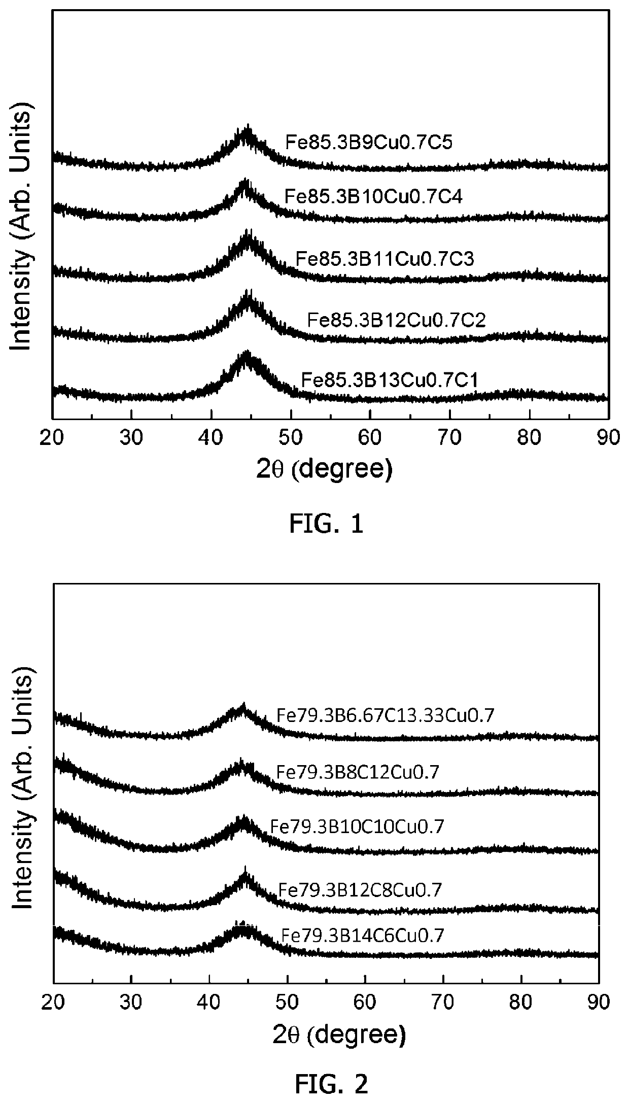
[0177]After raw materials of Fe, B, C and Cu were weighed such that an Fe master alloy represented by empirical formula Fe85.3B13C1Cu0.7 was manufactured, the Fe master alloy was manufactured by using an arc melting method. Thereafter, the manufactured Fe master alloy was melted, and then an Fe-based soft magnetic initial alloy having a ribbon form with a thickness of about 20 μm and a width of about 2 mm was manufactured by rapidly cooling the melted master alloy at a rate of 106 K / sec through melt spinning at a rate of 60 m / s under an Ar atmosphere.

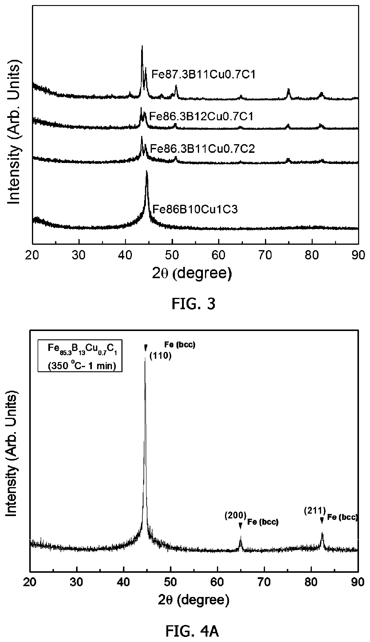
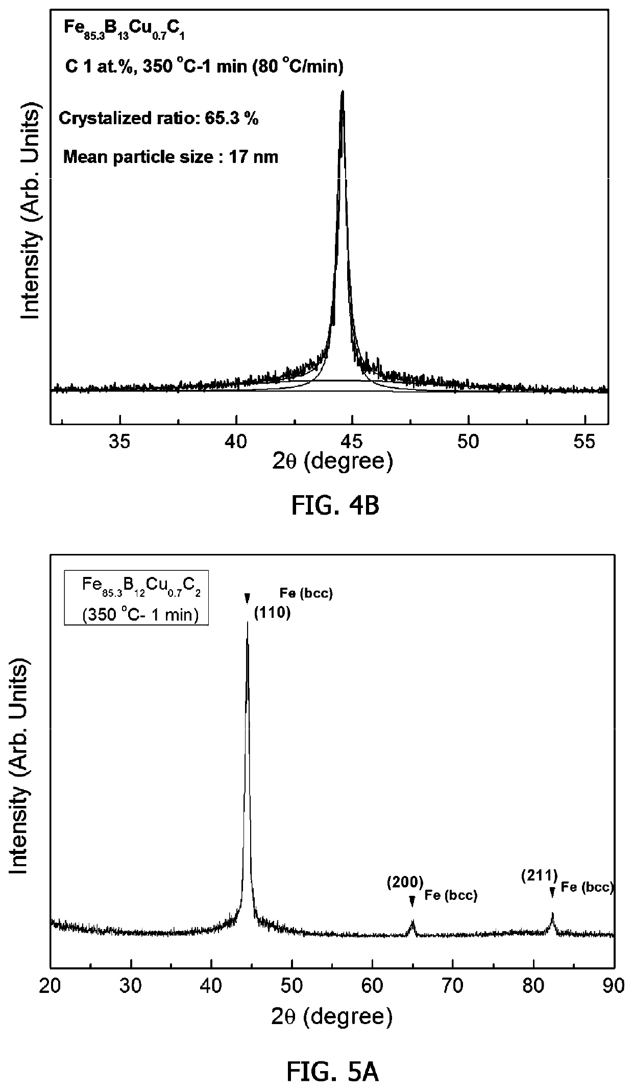
[0178]Thereafter, an Fe-based soft magnetic alloy as shown in the following Table 1 was manufactured by heat-treating the manufactured Fe-based soft magnetic initial alloy at a heating rate of 80° C. / min at room temperature and maintaining the heat-treated initial alloy at 350° C. for 1 minute.

examples 2 to 52

[0179]Fe-based soft magnetic initial alloys and Fe-based soft magnetic alloys as shown in the following Tables 1 to 5 were manufactured by carrying out a process in the same manner as in Example 1, and changing the composition of the empirical formula and / or the heat treatment conditions as in the following Tables 1 to 5.

experimental example 1

[0181]For the compositions of the manufactured initial alloys and the alloys after the heat treatment in Examples 1 to 52, the following Mathematical Formulae 1 and 2 or Mathematical Formulae 3 and 4 were calculated according to the content of Fe, and the values thereof are shown in the following Tables 1 to 5.

[0182](1) In the empirical formula, when a is 82 to 86 at %, Mathematical Formulae 1 and 2

[0183]bc⁢c[Mathematical⁢⁢Formula⁢⁢1]ad4[Mathematical⁢⁢Formula⁢⁢2]

[0184](2) In the empirical formula, when a is 78.5 at % or more and less than 82.0 at %, Mathematical Formulae 3 and 4

[0185]5⁢bc⁢c[Mathematical⁢⁢Formula⁢⁢3]ad[Mathematical⁢⁢Formula⁢⁢4]


PUM

PropertyMeasurementUnit
average particle diameteraaaaaaaaaa
particle diameteraaaaaaaaaa
aaaaaaaaaa

Abstract

An Fe-based soft magnetic alloy is provided. The Fe-based soft magnetic alloy can be represented by empirical formula FeaBbCcCud, and in the empirical formula, a, b, c and d are atomic percent (at %) of the corresponding element and are respectively 78.5≤a≤86, 13.5≤b+c≤21 and 0.5≤d≤1.5. The alloy has a high saturated magnetic flux density, excellent high frequency characteristics and low coercivity, and thus greatly facilitates the development of use as high performance / high efficiency small / lightweight parts. Since manufacturing costs are very low and the components contained in an alloy are easily controlled in an alloy manufacturing process, thereby enabling mass production of the alloy, the present invention can be widely applied as magnetic parts of electric and electronic devices such as a high power laser, a high frequency power supply, a high-speed pulse generator, an SMPS, a high-pass filter, a low-loss high frequency transformer, a fast switch and wireless charging.

Description

CROSS-REFERENCE TO RELATED APPLICATIONS[0001]This application is a national phase application under 35 U.S.C. § 371 of International Application No. PCT / KR2017 / 000231, filed Jan. 6, 2017, which claims priority to and the benefit of Korean Patent Applications No. 10-2016-0001749, filed Jan. 6, 2016, No. 10-2016-0001752, filed Jan. 6, 2016, and No. 10-2016-0001754, filed Jan. 6, 2016. The contents of the referenced patent applications are incorporated into the present application by reference.TECHNICAL FIELD OF THE DISCLOSURE[0002]The present invention relates to an Fe-based soft magnetic alloy, and more particularly, to an Fe-based soft magnetic alloy having a high saturated magnetic flux density and low magnetic loss, a manufacturing method therefor, and magnetic parts using the Fe-based soft magnetic alloy.DESCRIPTION OF RELATED ART[0003]A soft magnetic material is a material for magnetic cores such as various transformers, choke coils, various sensors, saturable reactors, and magn...

Claims


Application Information

Patent Timeline
Patent Type & Authority Patents(United States)
IPC IPC(8): C22C38/16H01F3/08H01F1/153H01F27/24H01F27/28H01F1/147C21D6/00
CPCC22C38/16C21D6/00H01F1/153H01F3/08H01F27/24H01F27/28C22C2200/04C22C2202/02H01F1/147C22C19/00C22C38/02C22C38/10H01F17/04H01Q1/52H05K9/00
Inventor KIM, JONG RYOULKANG, MINKIM, WOO CHULOH, HAN HOSONG, YONG-SUL
Owner AMOGREENTECH CO LTD
Why Eureka
Try Eureka