

RF tag and method for producing same
a technology of rf which is applied in the direction of synthetic resin layered products, computer peripheral equipment, metal layered products, etc., can solve the problems of difficult communication between rf tags and rf tags, harsh environment use of rf tags, and inability to meet the requirements of rf tags, so as to achieve efficient production and improve interlayer bonding strength
- Summary
- Abstract
- Description
- Claims
- Application Information
AI Technical Summary
Benefits of technology
Problems solved by technology
Method used
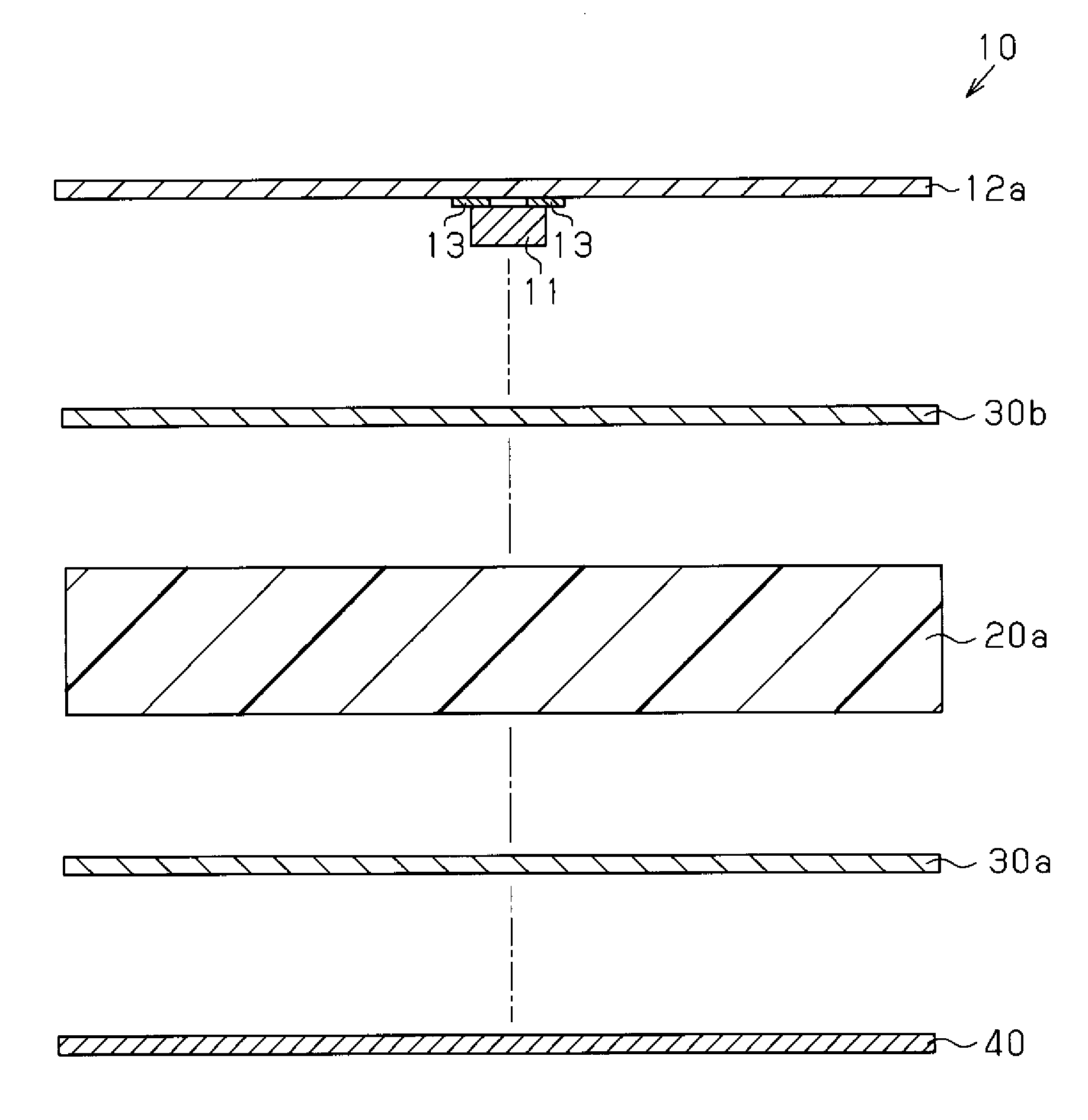
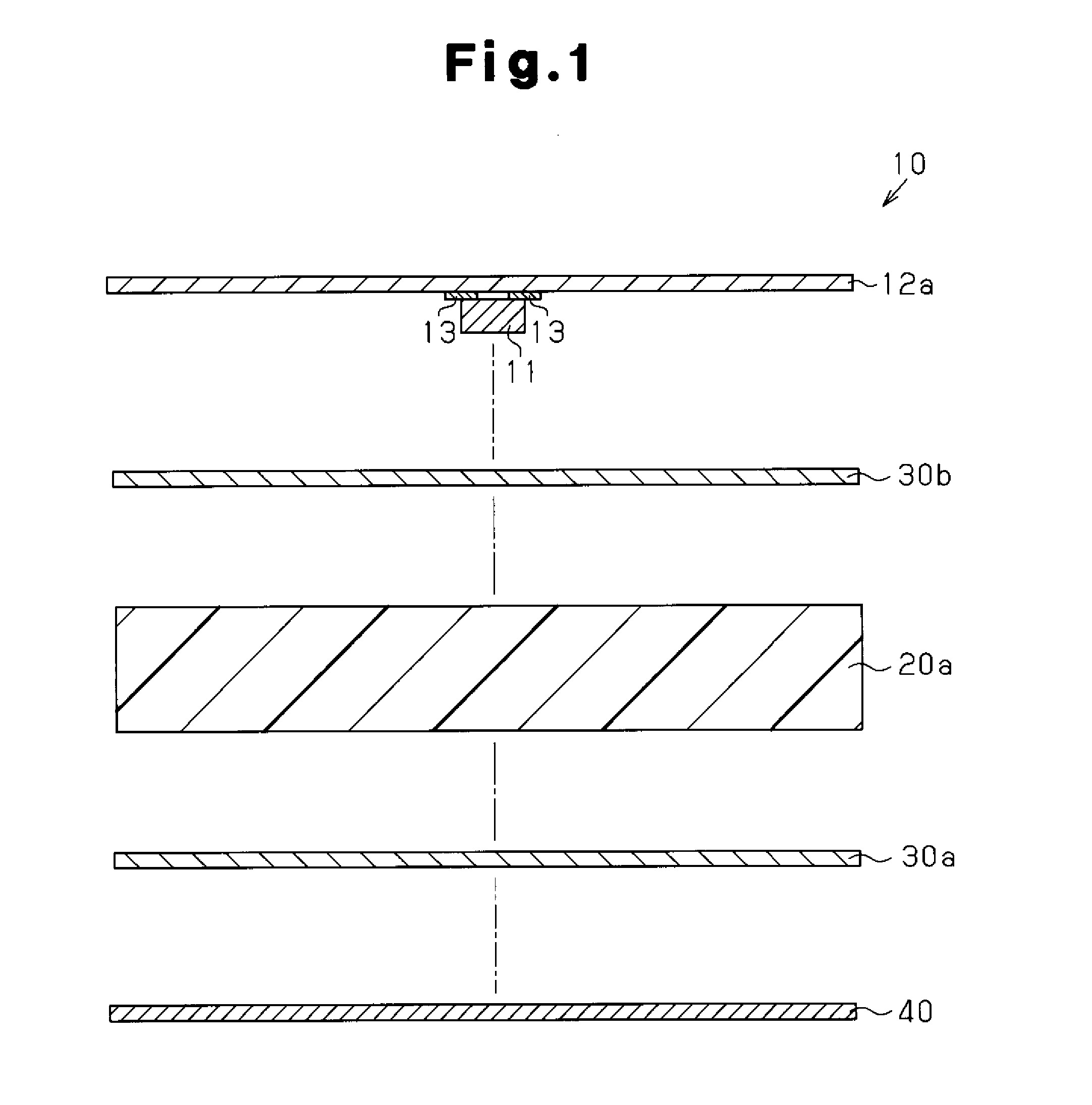
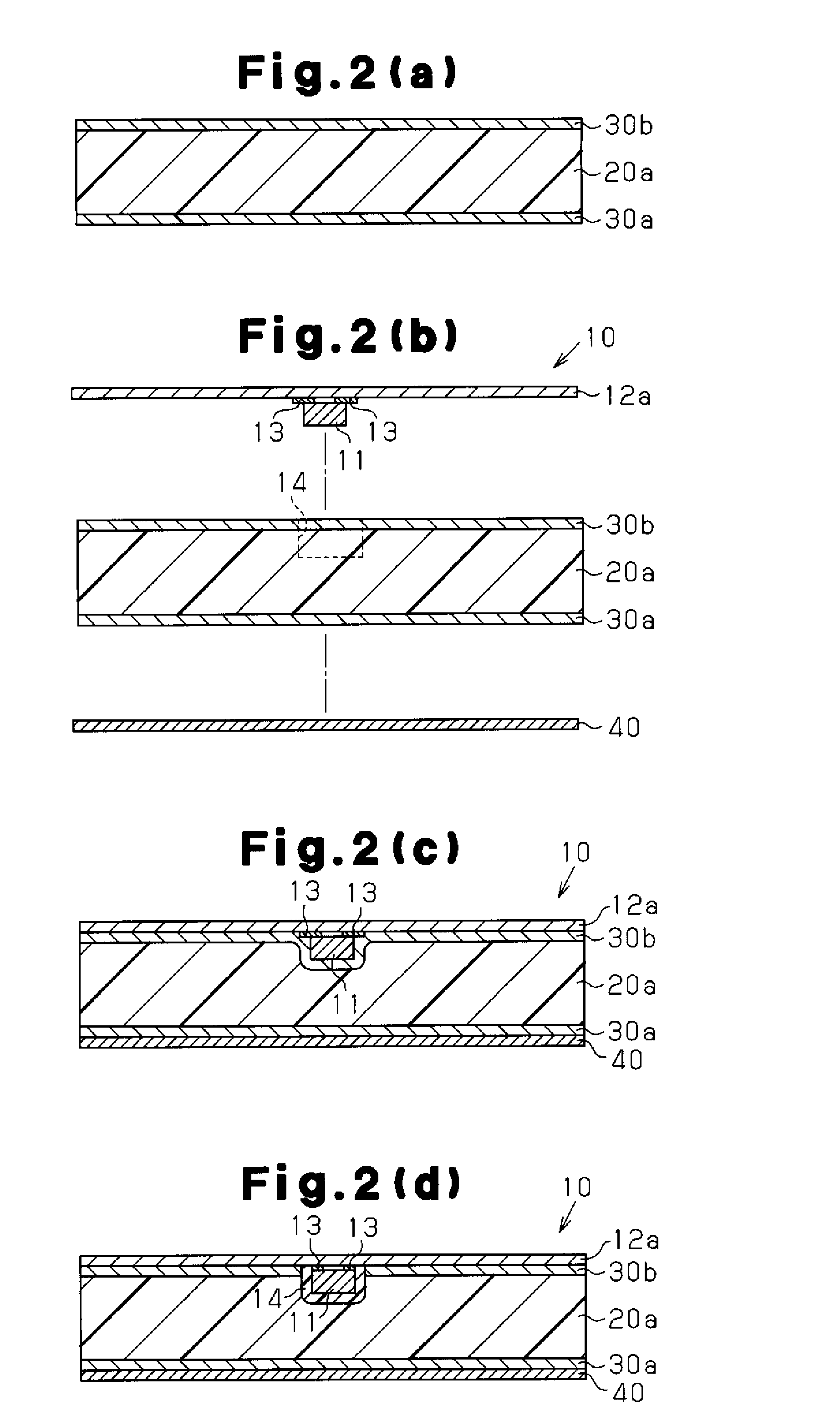
Image

Examples
synthesis example 1
Production of Graft Copolymer
[0084]First, 8,500 g of pure water was added to a stainless steel autoclave with an internal volume of 20 L, and 750 g of a 1% by mass aqueous solution of polyvinyl alcohol was dissolved therein as a suspending agent. Then, 3,500 g of polypropylene to be described below was added thereto and was stirred and dispersed. Aside from this, 10.0 g of benzoyl peroxide as a radical polymerization initiator and 37.5 g of t-butyl peroxymethacryloyloxyethyl carbonate as a radical copolymerizable organic peroxide were dissolved in 1,080 g of styrene, which is a monofunctional aromatic vinyl monomer, and 300 g of divinylbenzene, which is a bifunctional aromatic vinyl monomer. This solution was charged into the autoclave and was stirred.
[0085]The temperature of the autoclave was raised to 85 to 95° C. and was stirred for 2 hours to impregnate divinylbenzene and styrene containing benzoyl peroxide and t-butyl peroxymethacryloyloxyethyl carbonate into polypropylene. Aft...
synthesis examples 2 to 14
Production of Graft Copolymer
[0092]An aromatic vinyl monomer was graft-polymerized to various main chain structures by using the same method as that described in Synthesis Example 1 to obtain graft copolymers according to Synthesis Examples 2 to 14. The compositions of the graft copolymers are shown in Table 1.
TABLE 1Synthesis Examples:Dielectric Layer (20)1234567ComponentsMain chainNamePPTPXTPS6013PPPPPPTPS6015structure%7060857070 6085 Aromatic Mono-NameStStStStStStStvinylfunctional%2432122128.52814.25monomerMulti-NameDVBDVBDVBDVBDVBDVBDVBfunctional% 6 8 3 9 1.512 0.75Code NamePP7024TPX6032COC8512PP7021PP7028PP6028COC8514Synthesis Examples:Dielectric Layer (20)891011121314ComponentsMain chain NamePPPPPPPPPPTPXPPEstructure%905085 705090 70AromaticMono-NameStStStStStStStvinylfunctional% 84014.41830 9.824monomerMulti-NameDVBDVBDVBDVBDVBDVBDVBfunctional% 210 0.61220 0.2 6Code NamePP9008PP5040PP7014PP7018PP5030TPX9098PPE7024
Descriptions of abbreviations in Table 1 are as follows:
[0...
example 1
[0101]The graft copolymer obtained in Synthesis Example 1 was formed into a plate by using an injection molding machine (manufactured by TABATA Industrial Machinery Co., Ltd.) to produce a dielectric layer (90 mm in length, 50 mm in width, and 4 mm in thickness).
[0102]A glass epoxy prepreg sheet (manufactured by Panasonic Electric Works Co., Ltd., R-1661, 90 mm in length, 50 mm in width, and 10 mm in thickness) for forming a prepreg layer was arranged on each surface of the dielectric layer. Thermal compression bonding was performed at 150° C. by using a vacuum pressing machine (manufactured by KITAGAWA SEIKI CO., LTD.) to produce a prepreg plate.
[0103]An IC chip (storage medium) was mounted on rolled copper foil (manufactured by Fukuda Metal Foil & POWDER Co., LTD., 90 mm in length, 40 mm in width, and 18 μm in thickness) to produce an antenna circuit.
[0104]A recessed portion (with a diameter of 5 mm and a depth of 1 mm) was formed at one surface of the prepreg plate by using a dri...
PUM
| Property | Measurement | Unit |
|---|---|---|
| carbon number | aaaaa | aaaaa |
| decomposition temperature | aaaaa | aaaaa |
| thickness | aaaaa | aaaaa |
Abstract
Description
Claims
Application Information