Multi-substrate liquid metal high-frequency switching device

Inactive Publication Date: 2005-08-09
AGILENT TECH INC
View PDF9 Cites 6 Cited by
  • Summary
  • Abstract
  • Description
  • Claims
  • Application Information

AI Technical Summary

Benefits of technology

[0015]The present invention provides a device and manufacturing method that comprises forming first and second substrates joined and comprising a main channel provided in at least one of the substrates and a connecting channel provided in at least one of the substrates, the connecting channel connected to the main channel, and the main channel having spaced apart electrodes and at least partially filled with li

Problems solved by technology

The reed micro-relay has problems related to large size and relatively short service life.
As to the first problem, the reeds not only require a relatively large space, but also do not perform well during high-frequency switching due to their size and electromagnetic response.
As to the second problem, the flexing of the reeds due to biasing and attraction causes mechanical fatigue, which can lead to breakage of the reeds after extended use.
However, these contacts would fail over time.
This solved the problem of contact failure, but the problem of mechanical fatigue of the reeds remained unsolved.
The major dra

Method used


Image

  • Multi-substrate liquid metal high-frequency switching device
  • Multi-substrate liquid metal high-frequency switching device
  • Multi-substrate liquid metal high-frequency switching device

Examples


Embodiment Construction

[0025]The term “horizontal” as used in herein is defined as a plane parallel to the major surface of a substrate, regardless of its orientation. Terms, such as “top”, “bottom”, “above”, “below”, “over”, and “under” are defined with respect to the horizontal plane.

[0026]In the following description, numerous specific details are given to provide a thorough understanding of the invention. However, it will be apparent that the invention may be practiced without these specific details. In order to avoid obscuring the present invention, some well-known configurations and process steps are not disclosed in detail.

[0027]In addition, the drawings showing embodiments of the apparatus are semi-diagrammatic and not to scale and, particularly, some of the dimensions are for the clarity of presentation and may be exaggerated in the drawing FIGs. The same numbers will be used in all the drawing FIGs. to relate to the same elements.

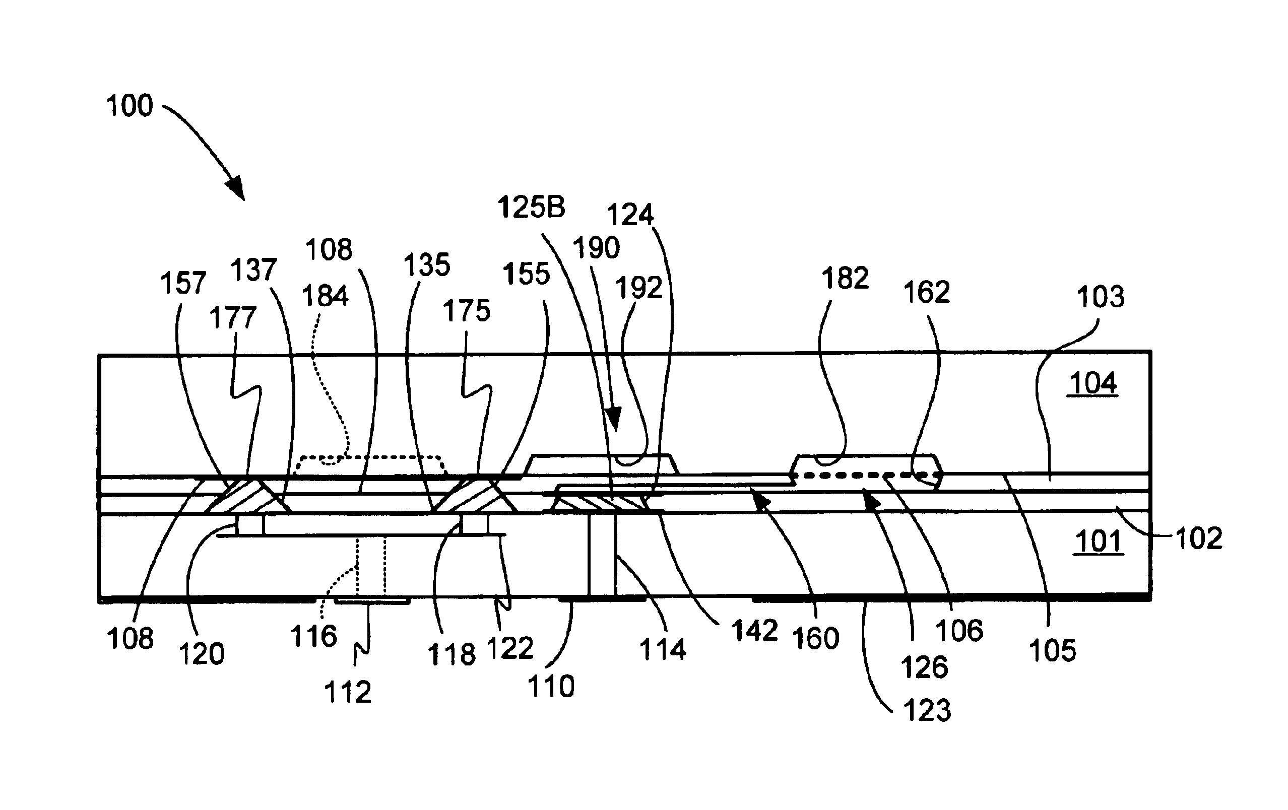
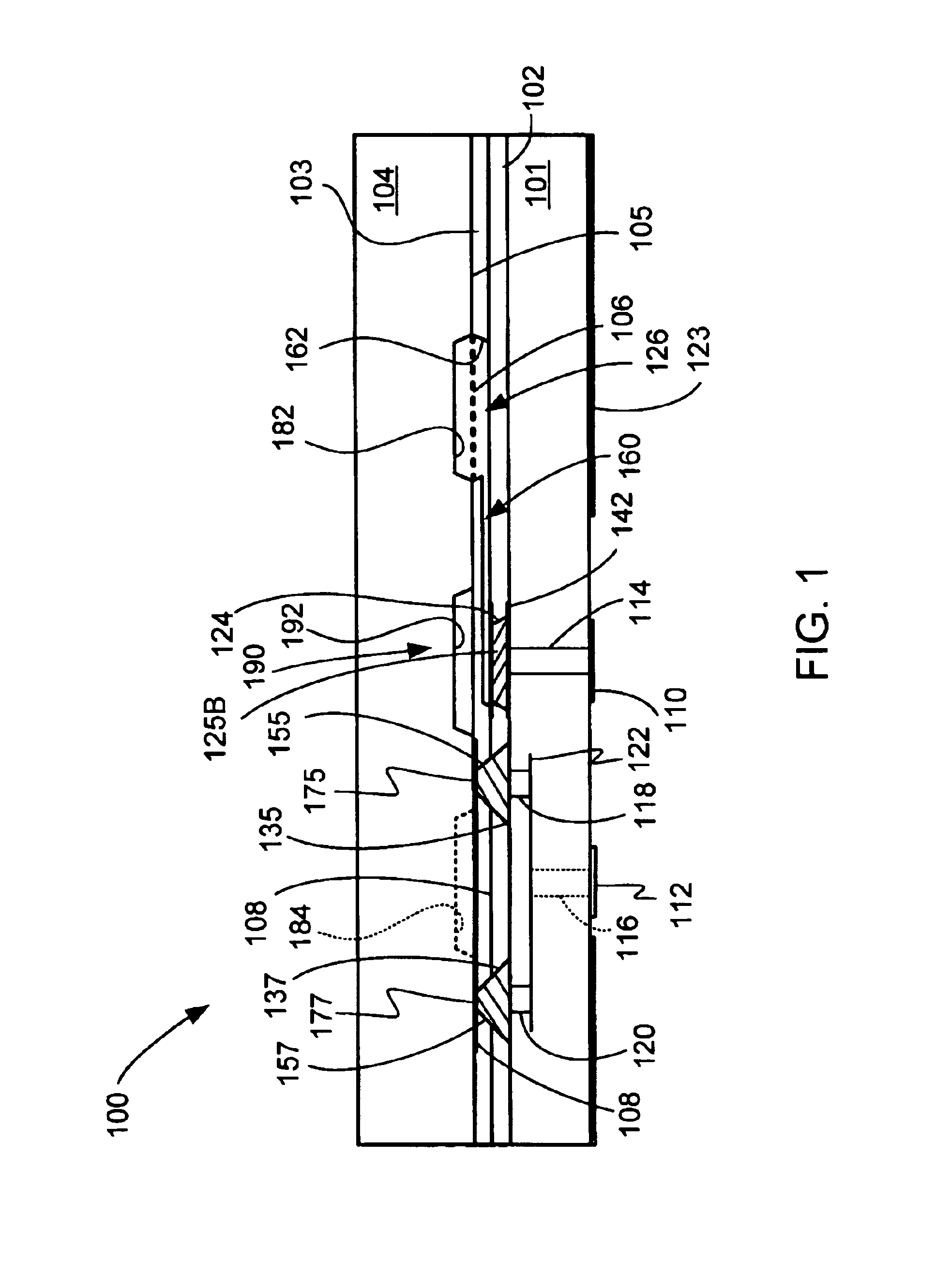
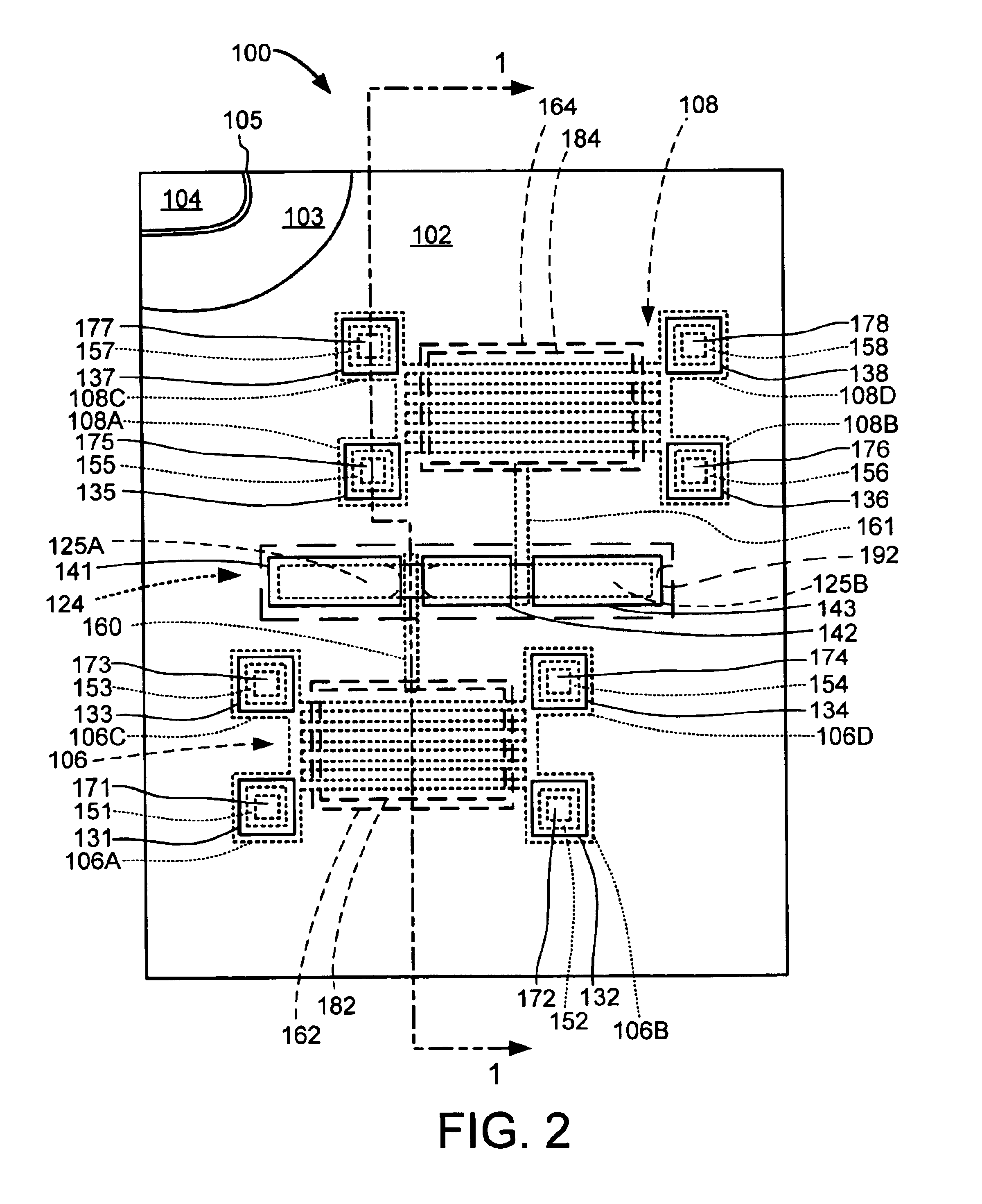
[0028]Referring now to FIGS. 1 and 2, therein are shown a cross-se...


PUM


Abstract

A device and manufacturing method are provided that comprises forming first and second substrates joined together and comprising a main channel provided in at least one of the substrates and a connecting channel provided in at least one of the substrates, the connecting channel connected to the main channel, and the main channel having spaced apart electrodes and at least partially filled with liquid metal. The method further comprises forming a heater substrate comprising a suspended heater element in fluid communication with the connecting channel, the suspended heater element operable to cause a fluid non-conductor to separate the liquid metal and selectively interconnect the electrodes, and providing a high-frequency signal loss reduction structure between the main channel and the heater substrate.

Description

CROSS-REFERENCE TO RELATED APPLICATIONS[0001]The present application contains subject matter related to a concurrently filed U.S. patent application Ser. No. 10 / 738,665 by Tsutomu Takenaka and You Kondoh entitled “SURFACE JOINED MULTI-SUBSTRATE LIQUID METAL SWITCHING DEVICE”.BACKGROUND[0002]1. Technical Field[0003]The present invention relates to an electrical device, and more specifically to a liquid metal micro-relay device.[0004]2. Background Art[0005]There are many different types of electrical micro-relay devices, and one popular type is the reed micro-relay, which is a small, mechanical contact type of electrical micro-relay device. A reed micro-relay has two reeds made of a magnetic alloy sealed in an inert gas inside a glass vessel surrounded by an electromagnetic driver coil. When current is not flowing in the coil, the tips of the reeds are biased to break contact and the device is switched off. When current is flowing in the coil, the tips of the reeds attract each other ...

Claims


Application Information

Patent Timeline
IPC IPC(8): H01H1/00H01H29/00H01H29/28H01H61/00H01H61/02H01H11/02H01H29/02H01H29/30H01H61/01
CPCH01H1/0036H01H29/28H01H61/02H01H2029/008H01H2061/006
Inventor KONDOH, YOUTAKENAKA, TSUTOMU
Owner AGILENT TECH INC
Why Eureka
Try Eureka