Steering system

a steering system and rack technology, applied in the direction of electric steering, power steering, vehicle components, etc., can solve the problems of low accuracy in accurately estimating the axial force of the rack depending on the conditions of the road surface, and achieve the effect of accurately estimating the friction torque and low accuracy in estimating

Active Publication Date: 2022-07-26
JTEKT CORP
View PDF8 Cites 0 Cited by
  • Summary
  • Abstract
  • Description
  • Claims
  • Application Information

AI Technical Summary

Benefits of technology

[0004]The technique described in JP 2017-226318 A has shortcomings: it cannot accurately estimate a friction torque, and therefore has low accuracy in estimating a rack axial force depending on the conditions of a road surface or a tire. The present disclosure provides a steering system that can accurately estimate a friction torque occurring in the steering system.
[0006]In this aspect, the combined friction torque is calculated using the tooth flank normal force calculation part that calculates a normal force acting on the tooth flank of the first transmission device, the friction coefficient and the tooth flank normal force of the first transmission device, and the one or more preset correction factors. Thus, a friction torque occurring in the steering system can be accurately estimated. Moreover, calculation of the combined friction torque is simplified compared with when the friction torques occurring in the respective transmission devices are separately calculated using individual meshing models and then the calculated friction torques are combined.

Problems solved by technology

The technique described in JP 2017-226318 A has shortcomings: it cannot accurately estimate a friction torque, and therefore has low accuracy in estimating a rack axial force depending on the conditions of a road surface or a tire.

Method used


Image

  • Steering system
  • Steering system
  • Steering system

Examples


Embodiment Construction

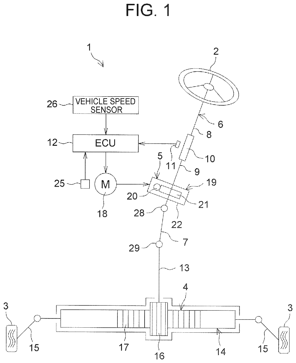
[0024]An embodiment of the present disclosure will be described in detail below with reference to the accompanying drawings. FIG. 1 is a schematic view showing a schematic configuration of an electric power steering system to which a steering system according to an embodiment of the present disclosure is applied. An electric power steering device (steering system) 1 is a column-assist electric power steering system (hereinafter referred to as a “column EPS”) in which an electric motor and a speed reducer are disposed on a column part.

[0025]The column EPS 1 includes a steering wheel 2 as a steering member used to steer a vehicle, a wheel turning mechanism 4 that turns wheels-to-be-turned 3 in conjunction with rotation of the steering wheel 2, and a steering assisting mechanism 5 that assists a driver in steering. The steering wheel 2 and the wheel turning mechanism 4 are mechanically coupled to each other through a steering shaft 6, a first universal joint 28, an intermediate shaft 7...


PUM


Abstract

Provided is a steering system including a controller that controls an electric motor. The controller has a combined friction torque estimation unit that estimates a combined friction torque combining friction torques occurring in respective transmission devices including a first transmission device. The combined friction torque estimation unit has a slipping speed calculation part that calculates a slipping speed of the first transmission device based on an angular speed of the electric motor, a friction coefficient calculation part that calculates a friction coefficient of the first transmission device based on the slipping speed, a tooth flank normal force calculation part that calculates a normal force acting on a tooth flank of the first transmission device, and a friction torque calculation part that calculates the combined friction torque using the friction coefficient, the tooth flank normal force, and one or more preset correction factors.

Description

CROSS-REFERENCE TO RELATED APPLICATION[0001]This application claims priority to Japanese Patent Application No. 2019-056999 filed on Mar. 25, 2019, incorporated herein by reference in its entirety.BACKGROUND1. Technical Field[0002]The present disclosure relates to a steering system.2. Description of Related Art[0003]In the fields of controlling an assisting torque in an electric power steering system (EPS) and controlling a reaction force torque in a steer-by-wire system, a technique has been developed that estimates a reaction force from a road surface and a rack axial force using signals from sensors, installed in an EPS and a vehicle, to transmit information on the road surface to a driver and thereby improve the steering performance. For example, Japanese Patent Application Publication No. 2017-226318 (JP 2017-226318 A) discloses a technique of estimating a rack axial force using information (a motor current, a motor angle, and a steering torque) from sensors installed in an EPS...

Claims


Application Information

Patent Timeline
Patent Type & Authority Patents(United States)
IPC IPC(8): B62D6/10B62D5/04B62D6/00
CPCB62D6/10B62D5/0421B62D6/006B62D5/046B62D6/00B62D5/0481B62D6/008B62D5/0409
Inventor HIGASHI, MASAYASUMIKI, DAISUKEFUCHS
Owner JTEKT CORP
Why Eureka
Try Eureka