
Seal chain

Active Publication Date: 2022-11-15
TSUBAKIMOTO CHAIN CO
View PDF16 Cites 0 Cited by
  • Summary
  • Abstract
  • Description
  • Claims
  • Application Information

AI Technical Summary

Benefits of technology

The invention helps to seal the area between a bushing and a roller in a good way.

Problems solved by technology

Thus, the parts between the bushings and the rollers are not sealed in a favorable manner.
This will cause lubricant between the bushings and the rollers to easily leak to the outside through a part between the inner surface of each inner plate and the end surface of the roller.
In addition, external foreign matter will easily enter the parts between the bushings and the rollers through the part between the inner surface of each inner plate and the end surface of the roller.

Method used


Image

  • Seal chain
  • Seal chain
  • Seal chain

Examples


Embodiment Construction

[0023]A seal chain according to an embodiment will now be described with reference to the drawings.

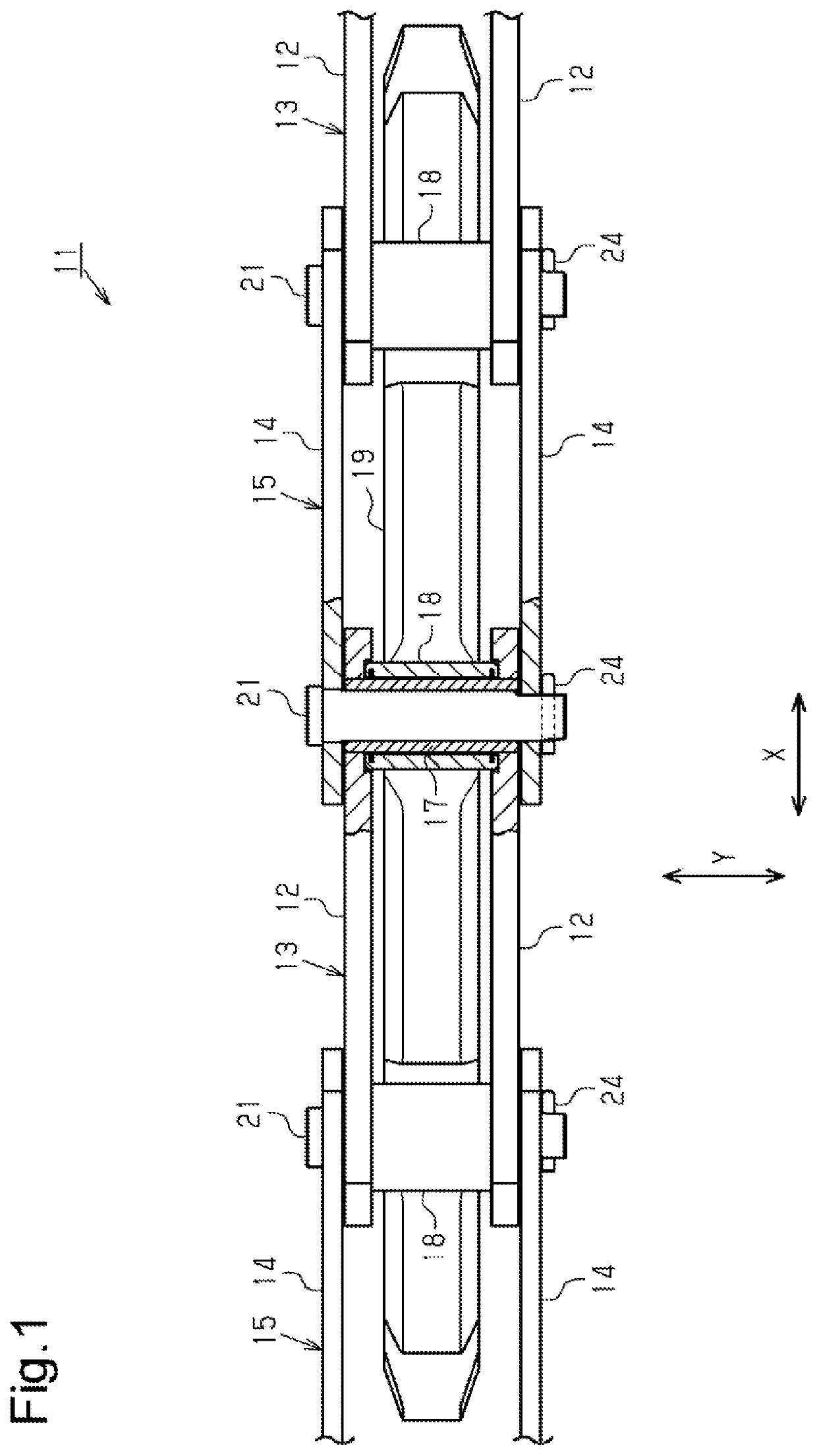
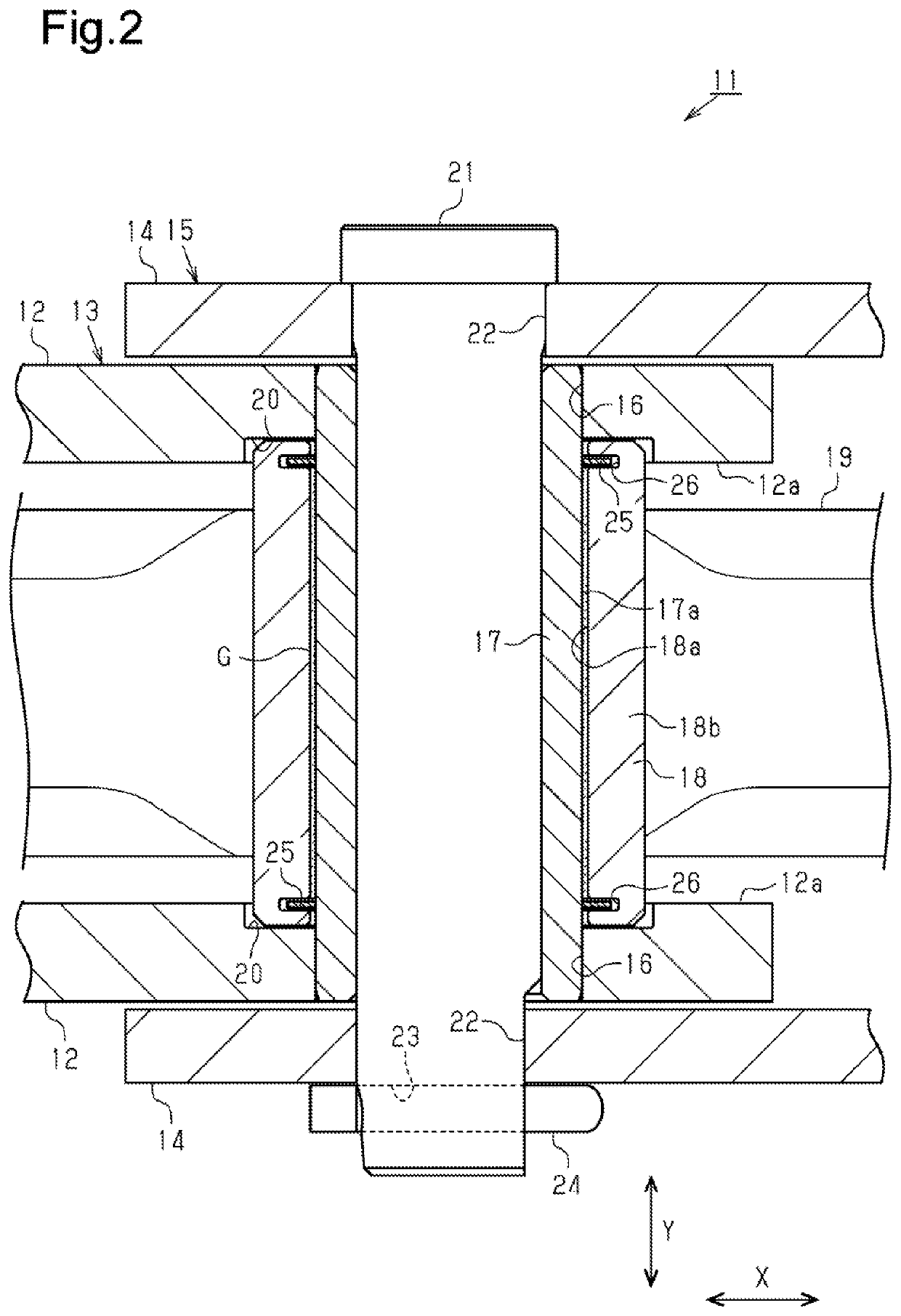
[0024]Referring to FIG. 1, a seal chain 11 is made of, for example, a steel material and includes inner links 13 and outer links 15. Each inner link 13 includes two inner link plates 12 opposed to and spaced apart from each other in a width direction Y. Each outer link 15 includes two outer link plates 14 arranged to externally hold the two inner link plates 12 in between in the width direction Y.

[0025]The inner link plates 12 of each inner link 13 and the outer link plates 14 of each outer link 15 have a substantially rectangular shape extending in a serial arrangement direction X, which is a movement direction when the seal chain 11 is pulled to move from one side in a longitudinal direction orthogonal to the width direction Y. The inner link plates 12 and the outer link plates 14, which are opposed to each other in the width direction Y, are parallel to each other. Thus, the seal ch...


PUM


Abstract

A seal chain includes two inner link plates opposed to and spaced apart from each other, a tubular bushing, opposite ends of the bushing being respectively joined to the two inner link plates, a pin rotationally inserted into the bushing, a tubular roller into which the bushing is inserted, the roller being rotationally supported by the bushing, and two outer link plates arranged to externally hold the two inner link plates in between, opposite ends of the pin being respectively joined to the two outer link plates. A recess into which an end of the roller is inserted is formed in an inner surface of each of the inner link plates.

Description

BACKGROUND OF THE INVENTION[0001]The present invention relates to a seal chain having a sealing structure that seals a part between a bushing and a roller.[0002]Patent Document 1 describes a typical example of a seal chain. In such a seal chain, two inner plates and two outer plates are alternately combined with one another by inserting columnar pins into tubular bushings to be rotational relative to each other. The bushings are coupled to the opposite ends of the two inner plates to be non-rotational relative to each other, and the pins are coupled to the opposite ends of the two outer plates to be non-rotational relative to each other. A tubular roller is rotationally coupled to each bushing.PRIOR ART DOCUMENTPatent Document[0003]Patent Document 1: Japanese Laid-Open Patent Publication No. 2014-152908SUMMARY OF THE INVENTION[0004]The above-described seal chain does not particularly include a sealing structure that seals parts between the bushings and the rollers. Thus, the parts b...

Claims


Application Information

Patent Timeline
IPC IPC(8): F16G13/06F16J15/28
CPCF16G13/06F16J15/28F16G13/02F16J9/04F16J15/26
Inventor YASU, TAKUYAFUJIWARA, MAKOTONISHIZAWA, YUSUKE
Owner TSUBAKIMOTO CHAIN CO
Learn More