Portable soccer goal apparatus

Inactive Publication Date: 2001-10-25
TULIPANI VICTOR +1
View PDF0 Cites 21 Cited by
  • Summary
  • Abstract
  • Description
  • Claims
  • Application Information

AI Technical Summary

Problems solved by technology

Typically, these soccer nets are large, bulky, permanent or semi-permanent articles that are not readily disassembled for storage or transport.

Method used


Image

  • Portable soccer goal apparatus
  • Portable soccer goal apparatus

Examples


Embodiment Construction

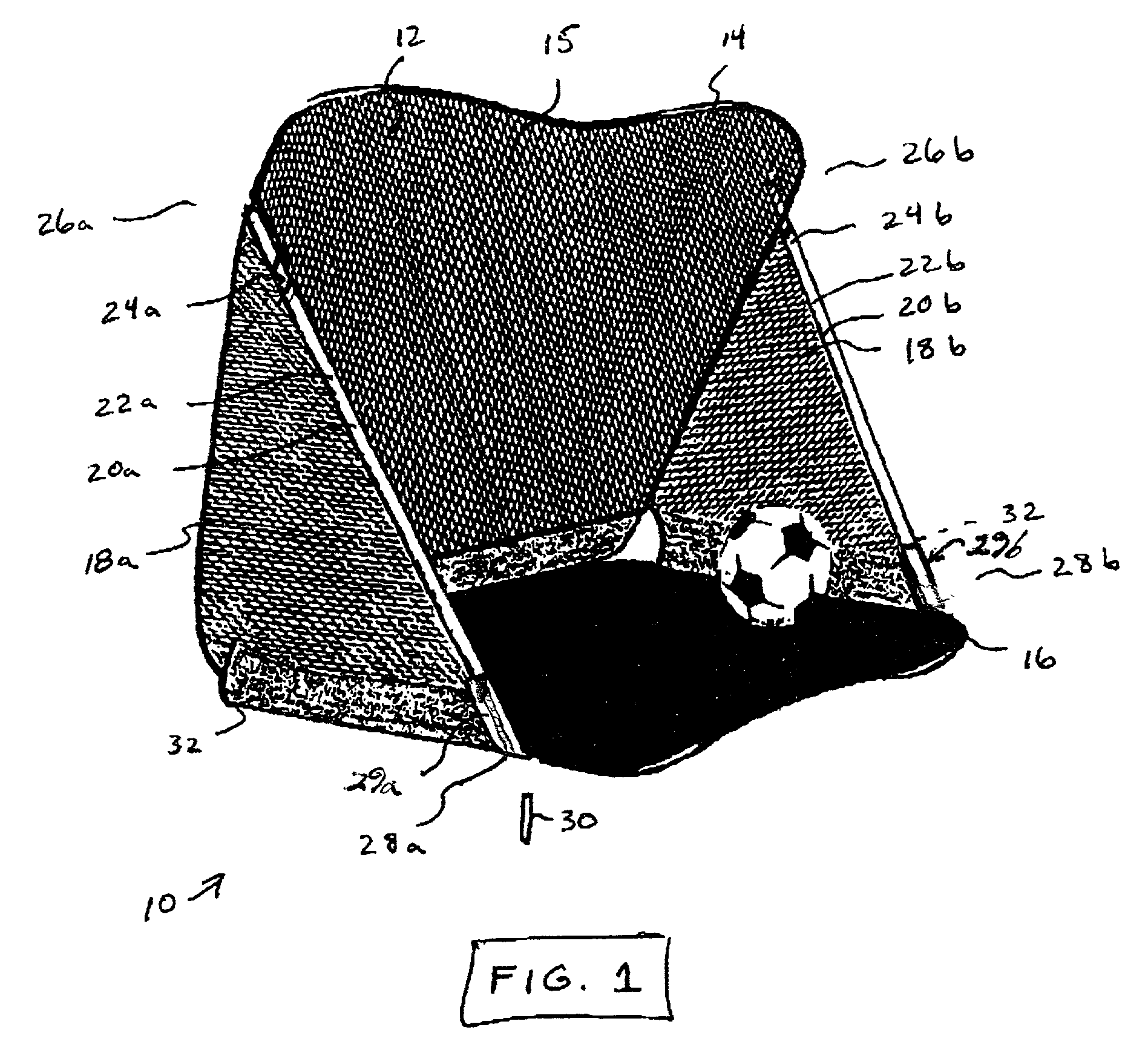
[0008] FIG. 1 is a perspective view of the portable soccer goal apparatus 10 of this invention as erected for use as a practice goal. Soccer goal 10 includes a net portion 12 (e.g. 70D.times.190T nylon or similar material) suspended within a frame 14, which is preferably a coated, flexible spring steel frame (e.g., 5 mm. by 2 mm.) covered with a protective material (e.g., 210D.times.110T oxford or similar material). The flexible and collapsible frame 14 effectively stretches the net 12 across its area to form a suitable back goal surface 15 (e.g., four feet by four feet), in the manner of a "pop-up" tent or similar structure. A base portion 16, also suspended within the frame 14, extends forward from the lower edge of the back portion 15, and a pair of side panels 18a, 18b extend between the upper part of the back portion 15 and the front part of the base portion 16. The expanded frame, with the back portion, base portion, and side panels extended therebetween, is further supported ...


PUM


Abstract

A portable soccer goal includes a net portion suspended within a flexible spring frame which stretches the net across its area to form a back portion as a suitable goal surface. A base portion is attached to the back portion, and a pair of side panels extend between the back portion and base portion. The expanded frame, with the net portion, base portion, and side panels extended therebetween, is stabilized by support rods inserted into sleeves extending between the upper portion of the back and the front portion of the base. Upper and lower sleeves cover the ends of the rods to prevent exposure to the players. Stakes and / or sand pockets may be used to secure the apparatus to the ground.

Description

[0001] 1. Field of the Invention[0002] This invention relates generally to sporting goods and accessories, and more specifically to an improved goal or net apparatus for use with the play and practice of soccer, football, field hockey, lacrosse, and other sports utilizing a net.[0003] 2. Discussion of Related Art[0004] Many sports such as soccer (football) utilize a goal or net structure for play. Typically, these soccer nets are large, bulky, permanent or semi-permanent articles that are not readily disassembled for storage or transport. It is therefore an object of this invention to provide a simple, inexpensive, lightweight, portable soccer / football net that can be easily disassembled and re-assembled for personal or temporary use at a variety of locations such as home, school, beach, or park.[0005] The portable soccer goal of this invention includes a net portion suspended within a flexible spring frame which effectively stretches the net across its area to form a suitable goal ...

Claims


Application Information

Patent Timeline
IPC IPC(8): A63B63/00
CPCA63B63/004A63B2210/50
Inventor TULIPANI, VICTORMENDICK, MARTY
Owner TULIPANI VICTOR
Why Eureka
Try Eureka