
Internet based emergency communication system

a communication system and emergency communication technology, applied in the field of emergency communication systems, can solve problems such as the inability of the remote monitoring entity to accurately communicate, the false alarms that may be caused, and the belief of neighbors that the alarm indication is "false"

Inactive Publication Date: 2002-01-17
CWITHIN +1
View PDF1 Cites 283 Cited by
  • Summary
  • Abstract
  • Description
  • Claims
  • Application Information

AI Technical Summary

Problems solved by technology

The primary problem with prior art security and emergency notification systems of the type described above relates to the inability of the remote monitoring entity to accurately verify an alarm indication.
Therefore, there are frequently false alarms that may be caused by any number of events, including but not limited to: 1) a faulty sensor; 2) a pet moving within the premises; 3) an authorized entrant that has mistakenly tripped a sensor unknowingly; 4) an authorized entrant that has failed to deactivate the system; 5) smoke from a stove or fireplace; or 6) a child at a premises who has inadvertently requested emergency medical assistance by depressing the emergency sequence on the keypad / display.
Frequent false alarms cause neighbors to believe that alarm indications are "false".
More importantly, a high number of false alarms cause police, fire and emergency services providers to react slowly believing the subject alarm indication to be false.
Another problem with these types of prior art systems is that information transmitted to the remote monitoring entity only relates to how an alarm indication was activated (i.e. through the activation and control panel or through a sensor).
Thus, if an actual emergency has occurred, the remote monitoring entity has no means of identifying what a perpetrator looks like, the location of a fire at the premises or the condition of person who has suffered a medical emergency.
Furthermore, systems of these types do not provide real time information to emergency services providers which can be transmitted to multiple interested parties at diverse and remote locations.
Nor, do these systems provide immediate notification of an alarm indication to a premises owner or manager who is not at the premises at the time of the alarm.
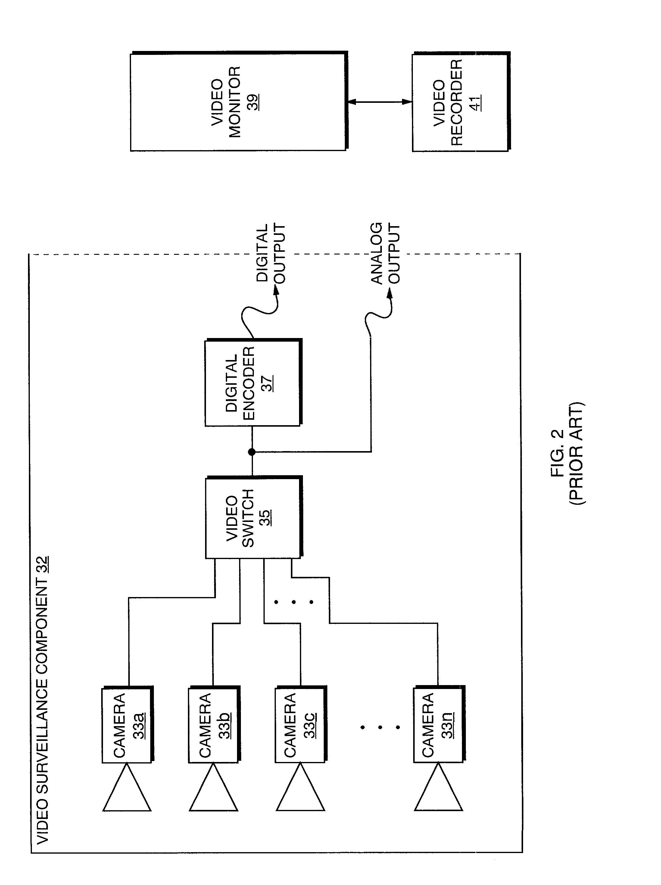
CCTV systems suffer from numerous problems: 1) they are not practical for use at residences or small businesses since continual recording of living and work environments is generally considered to be intrusive; 2) CCTV Systems require constant monitoring of transmitted video images in order to be effective in the prevention of crime, or early detection of an emergency.
Such a requirement necessitates expensive personnel who can provide monitoring services; 3) CCTV Systems do not possess the capability to automatically alert an off site premises owner or manager of an emergency condition at the premises; 4) CCTV Systems do not enable real time, secure viewing of video images by multiple interested parties, including emergency services providers who are located away from the premises but who have a temporary or recurring interest in the events transpiring at the premises; 5) CCTV Systems do not enable real time voice communication between multiple interested parties, including emergency services providers who are located away from the premises but who have a temporary or recurring interest in the events transpiring at the premises; 6) CCTV Systems provide information as an emergency event unfolds, but generally cannot provide early warning for such emergencies as fires or unauthorized intrusions unless constantly monitored.
IVSS suffer from numerous problems: 1) IVSS can transmit voice, data and video images to only one remote location at a time; 2) IVSS rely on low paid central station monitoring operators to control emergency conditions; 3) IVSS is not secure due to the capability for an interested party to "dial into" a system to view video images from a remote location; and 4) IVSS systems in their present form are limited to communications using conventional telephone lines.

Method used


Image

  • Internet based emergency communication system
  • Internet based emergency communication system
  • Internet based emergency communication system

Examples


Embodiment Construction

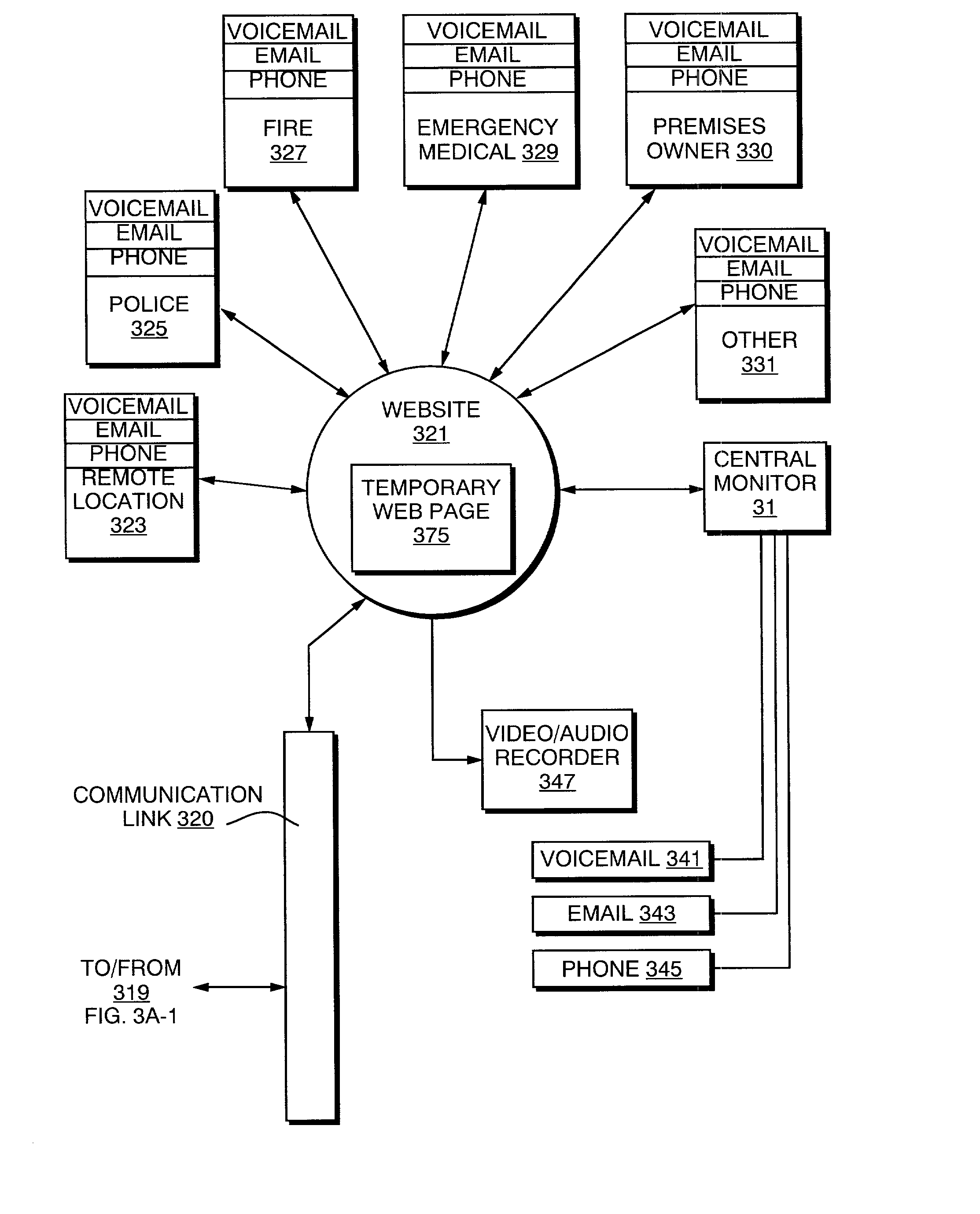
[0023] The present invention relates to security systems and methods, and more particularly, to security systems and methods using local video surveillance combined with transmission of recorded data such as video or audio sequences to an internet website from the secured premises. Throughout the drawings, like reference numerals are used to identify particular elements of the described systems and methods.

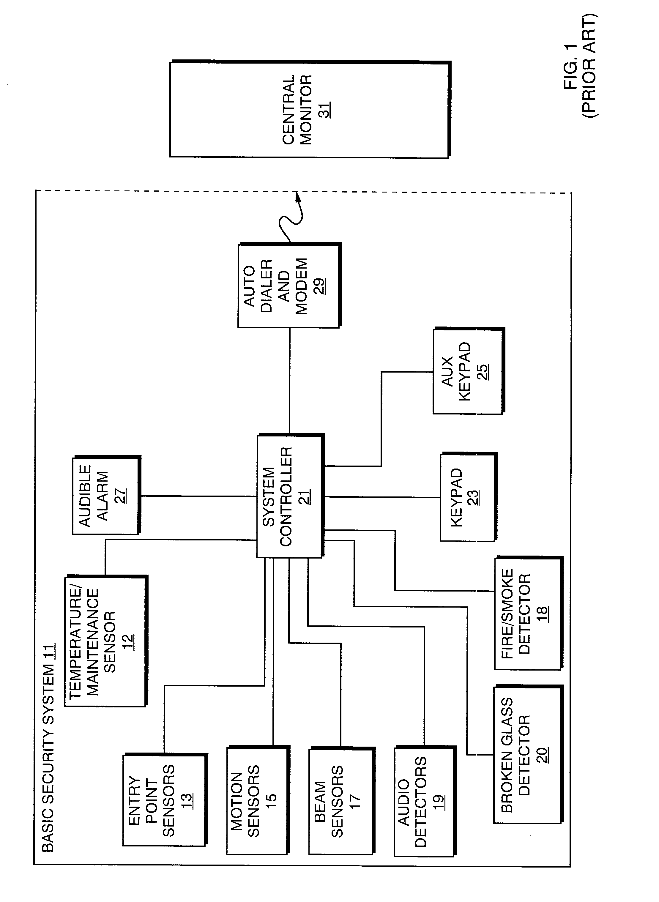
[0024] FIG. 1 is a block diagram of a prior art basic security system 11 for home or commercial use. Basic security system 11 includes temperature or other maintenance function (i.e. low heating fuel) sensors 12 and entry point sensors 13 that may be in the form of switches for detecting an open event at an entry point such as a door or a window. Basic system 11 may also include motion sensors 15 for detecting movement within the protected premises in the event that an entry point sensor is bypassed without being activated. In addition or as an alternative to motion sensors 15 are...


PUM


Abstract

The present invention provides a system for detecting an event within a premises and providing data such as live or recorded video, audio and data regarding that event to a website. The event may be an unauthorized entry to the premises, a fire, or a maintenance malfunction within the premises. The website may be accessed by a variety of authorized users including the owner or manager of the premises, a central monitor, local police, fire, or emergency medical personnel, or other entities specified by the owner or manager of the premises. The system permits authorized users to view the event in real time or as recorded on the website after the event has occurred to determine the type of event and an appropriate course of action to rectify it.

Description

RELATED CASES / INCORPORATION BY REFERENCE[0001] This is a continuation in part of U.S. patent application Ser. No. 09 / 545,948, filed Apr. 10, 2000. Applicant incorporates herein by reference U.S. patent application Ser. No. 09 / 545,948.[0002] The present invention relates to a method and apparatus for providing automatic, real-time or recorded, transmission of voice, data and video images from a premises to a single party or multiple interested parties using an internet website as a communications conduit. The website may be accessed only by interested parties that have been properly authorized. Access is made after an event has occurred comprising an intrusion, a fire and / or another type of emergency or other event at a premises.BACKGROUND INFORMATION[0003] Systems for detecting and reporting intrusions and other types of events including but not limited to fire and medical emergencies are well known in the prior art. A typical system for securing and protecting the occupants of a pr...

Claims


Application Information

Patent Timeline
Patent Type & Authority Applications(United States)
IPC IPC(8): G06F17/30G08B13/196G08B25/08H04L12/24H04N7/18
CPCG06F17/3089G08B13/19645G08B13/19656G08B13/19658G08B13/1968G08B13/19695G08B13/19697G08B25/08H04L41/0654H04N7/181G08B25/008G06F16/958
Inventor FOODMAN, BRUCE A.FOODMAN, HAROLD
Owner CWITHIN
Learn More