Fuel injection apparatus for an internal combustion engine

Inactive Publication Date: 2002-08-22
ROBERT BOSCH GMBH
View PDF5 Cites 6 Cited by
  • Summary
  • Abstract
  • Description
  • Claims
  • Application Information

AI Technical Summary

Problems solved by technology

However, the known valve member has the disadvantage that upon the opening of the valve member, a hydraulic force acts on the valve sealing face, and over the course of the opening stroke motion of the valve member this force is added to the

Method used


Image

  • Fuel injection apparatus for an internal combustion engine
  • Fuel injection apparatus for an internal combustion engine
  • Fuel injection apparatus for an internal combustion engine

Examples


Embodiment Construction

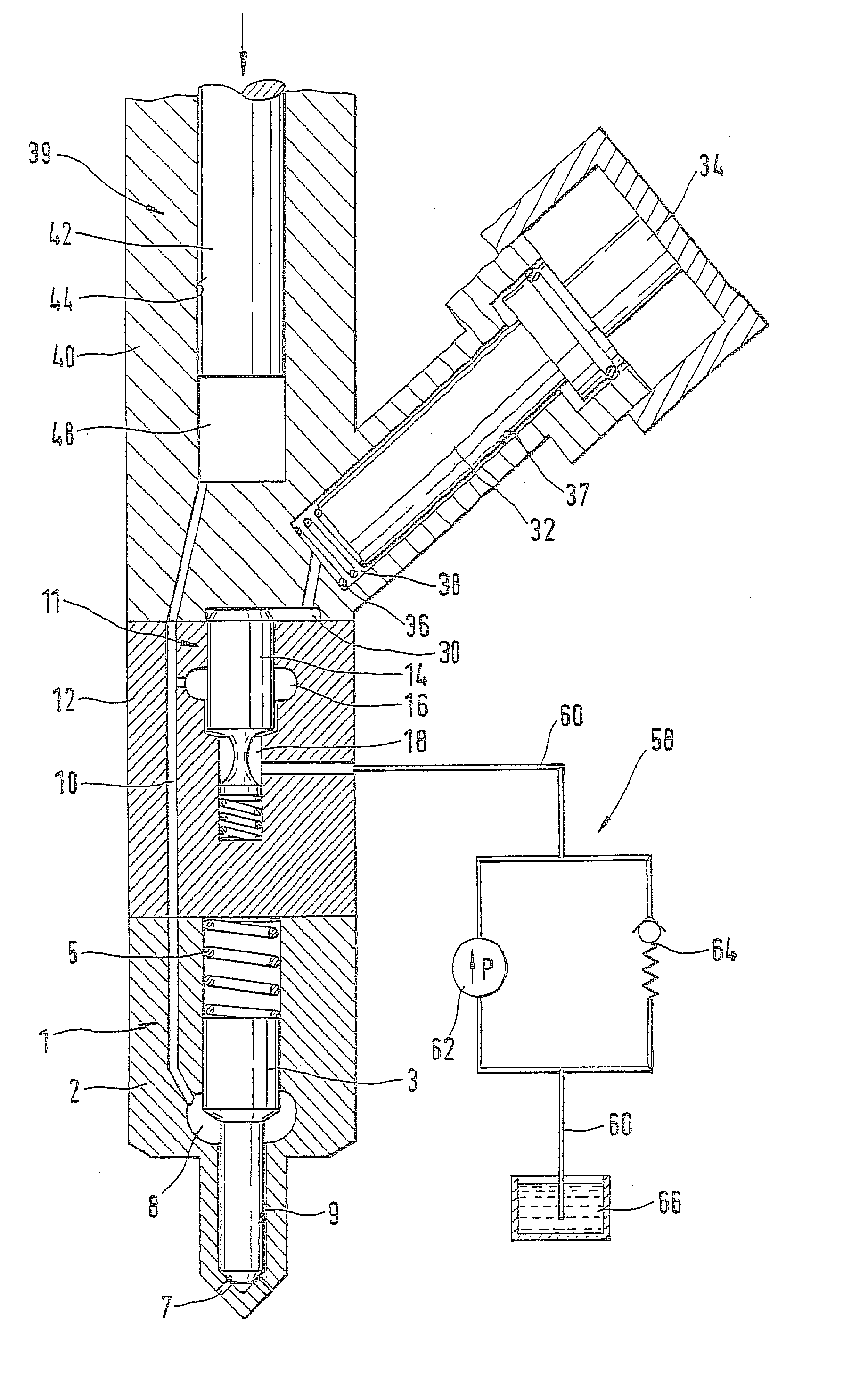
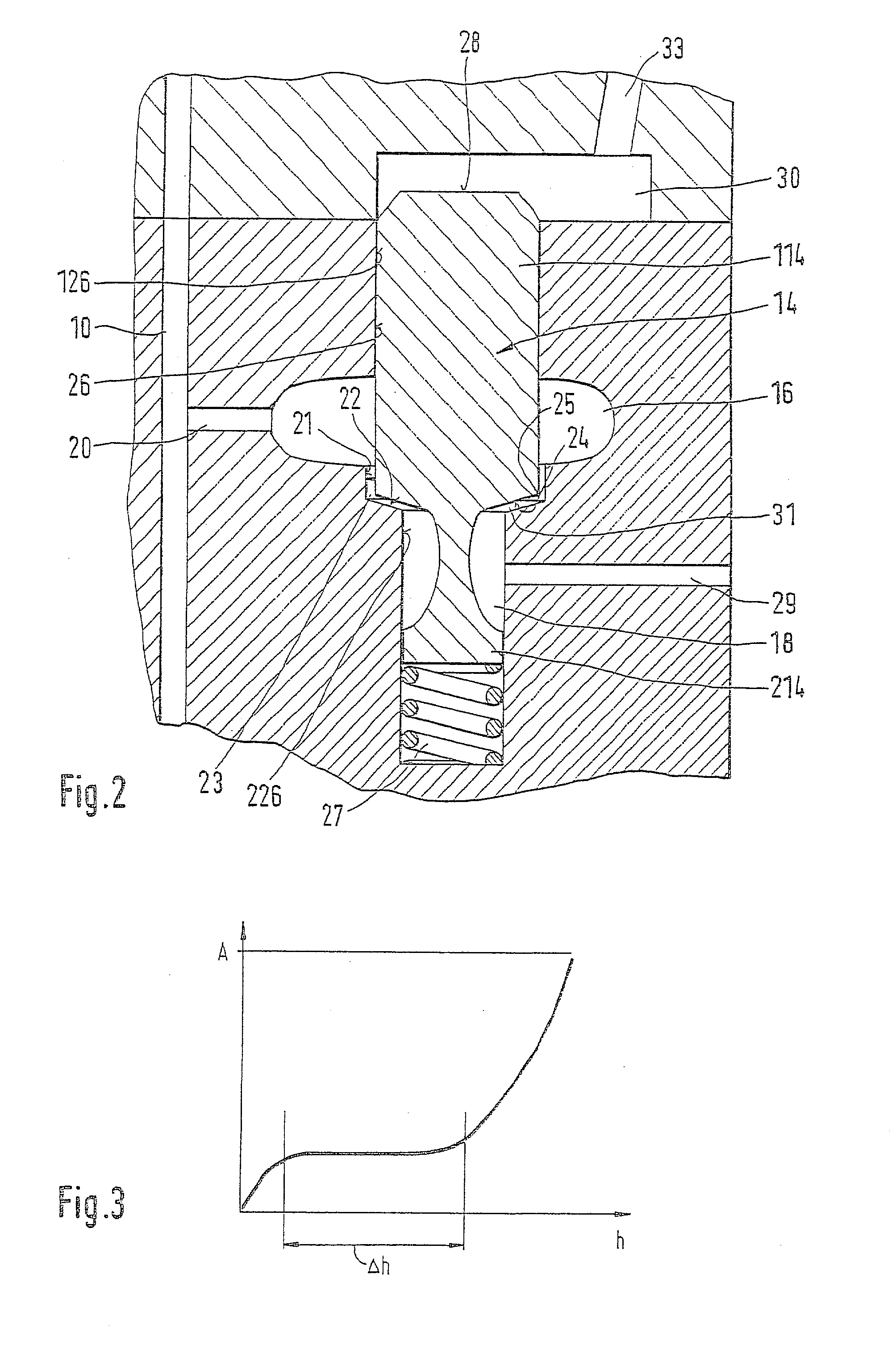
[0011] In FIG. 1, a longitudinal section is shown through a fuel injection apparatus of the invention, in the form of a unit fuel injector, of the kind used to inject fuel into the combustion chamber of an internal combustion engine, in particular a self-igniting internal combustion engine. The unit fuel injector contains all the components necessary for an injection; that is, a high-pressure-generating pump unit 39, an injection valve 1, and a control valve 11, which controls the onset and end of the injection. For the sake of clarity, FIG. 2 shows an enlargement of FIG. 1 in the region of the control valve 11. The structure of the individual components will be explained first below, and then their function as part of the unit fuel injector will be described.

[0012] The injection valve 1 includes an injection valve body 2, which is embodied essentially as a cylinder with a stepped diameter and protrudes with one end as far as the inside of the combustion chamber of an internal combu...


PUM


Abstract

The fuel injection apparatus has a pump unit (39), which pumps fuel at high pressure into a high-pressure conduit (10) communicating with an injection valve (1), and having a control valve (11), in which a pistonlike valve member (14) is guided with a sealing portion (114) in the bore (26), the sealing portion (114) being surrounded by a high-pressure chamber (16) that communicates with the pump work chamber (48). With one end, the valve member (14) protrudes one low-pressure chamber (18), which communicates with a fuel delivery system (58). A valve seat (22) is embodied in the bore (26) and cooperates with a valve sealing face (24), embodied on the valve member (14), to control the communication between the high-pressure chamber (16) and the low-pressure chamber (18). In terms of the fuel flow direction from the high-pressure chamber (16) to the low-pressure chamber (18), a throttle portion (21) is embodied in the bore (26) upstream of the valve seat (22) and with the sealing portion (114) of the valve member (14) forms a throttle gap (23), thus upon the opening stroke motion throttling the fuel flow in a stroke range of the valve member (14), so that upon the opening stroke motion of the valve member (14), no additional hydraulic forces can act on the valve member (14).

Description

PRIOR ART[0001] The invention is based on a fuel injection apparatus for an internal combustion engine. One such fuel injection apparatus in the form of a unit fuel injector is known from German Patent Disclosure DE 35 23 536 A1. For each combustion chamber of the engine, one unit fuel injector is provided, in which a pump unit, a control valve, and an injection valve are integrated to form a unit. The pump unit comprises a pump piston, which is driven synchronously with the engine and plunges into a pump work chamber, where it positively displaces the fuel located at high pressure therein. The pump work chamber communicates with the fuel injection apparatus, which opens at a certain fuel pressure and thus injects fuel at high pressure into the combustion chamber of the engine.[0002] The control valve disposed in the housing of the unit fuel injector opens and closes a communication between the pump work chamber and a fuel delivery system, in which a low fuel pressure prevails and w...

Claims


Application Information

Patent Timeline
IPC IPC(8): F02M45/12F02M57/02F02M59/36F02M59/46F02M61/10
CPCF02M45/12F02M57/02F02M59/366F02M59/468F02M2200/704
Inventor BECK, MATTHIAS
Owner ROBERT BOSCH GMBH
Why Eureka
Try Eureka