Inkjet device including ultrasonic vibrator for applying ultrasonic vibration to ink

a technology of ultrasonic vibration and inkjet, which is applied in the direction of printing, other printing apparatus, etc., can solve the problems of erratic printing results, easy cohesion of pigments in ink, and increase in molecular weight distribution

Inactive Publication Date: 2003-01-30
BROTHER KOGYO KK
View PDF0 Cites 21 Cited by
  • Summary
  • Abstract
  • Description
  • Claims
  • Application Information

AI Technical Summary

Problems solved by technology

Pigment-based inks have a problem in that the pigments in the ink can easily cohere with each other or settle out from the liquid base.
Polymeric inks have a problem in that over time the molecular-weight distribution can increase because of molecular coupling.
When these problems arise, printing results can be erratic and the ink nozzles can become clogged.
However, merely stirring up the ink does not sufficiently disperse pigments and molecular materials, so that problems, such as pigment sedimentation and cohesion, cannot be completely solved.

Method used


Image

  • Inkjet device including ultrasonic vibrator for applying ultrasonic vibration to ink
  • Inkjet device including ultrasonic vibrator for applying ultrasonic vibration to ink
  • Inkjet device including ultrasonic vibrator for applying ultrasonic vibration to ink

Examples


first embodiment

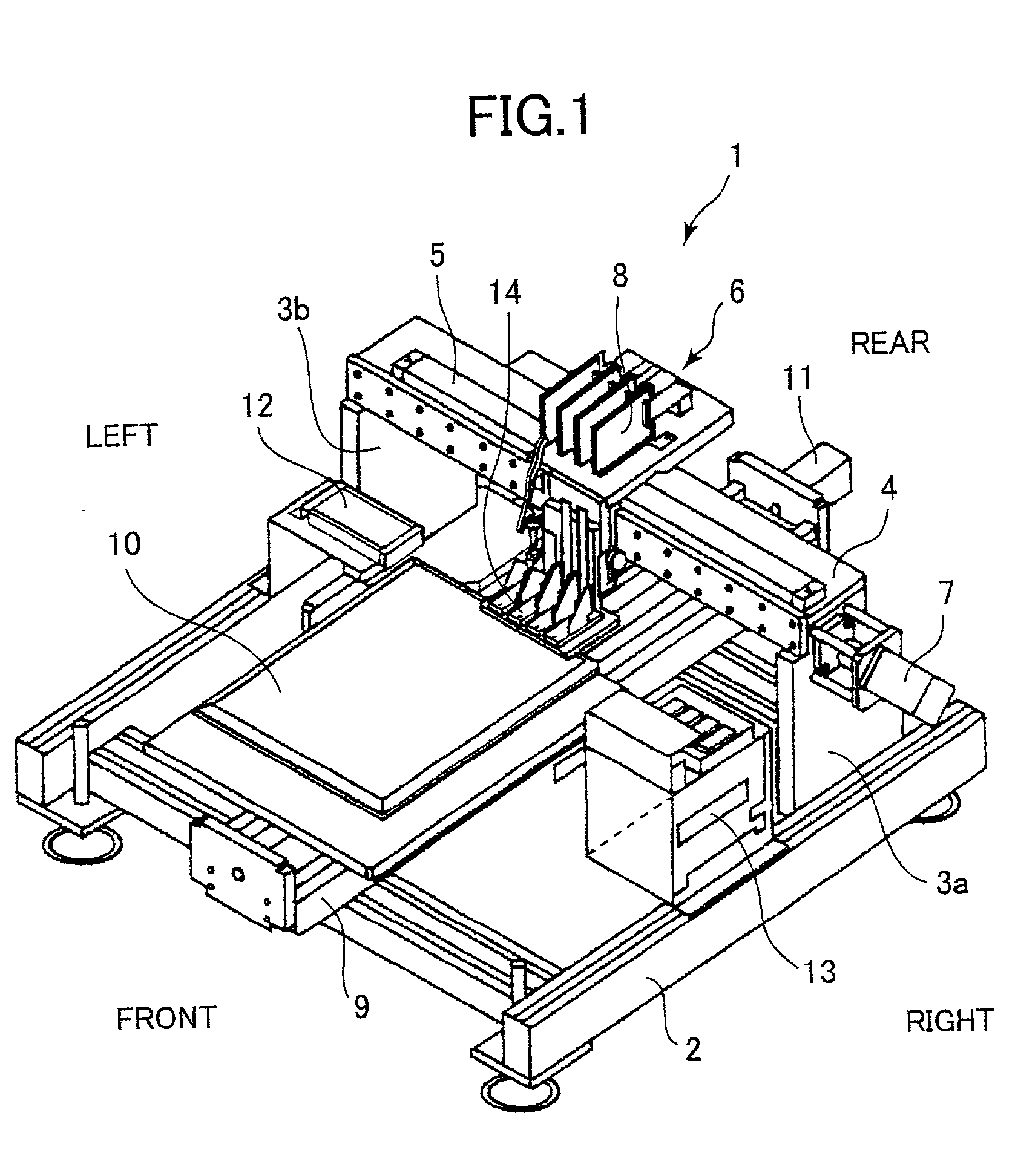
[0027] First, an inkjet printer 1 according to the present invention will be described. As shown in FIG. 1, the inkjet printer 1 includes a base frame 2, support frames 3a, 3b, an X-axis frame 4, and a linear scale 5. The base frame 2 is formed in a substantially rectangular shape, and the support frames 3a, 3b are disposed with an upright posture on a rear end of the base frame 2. The X-axis frame 4 spans between the support frames 3a and 3b. The linear scale 5 configures the X-axis of the X-axis frame 4.

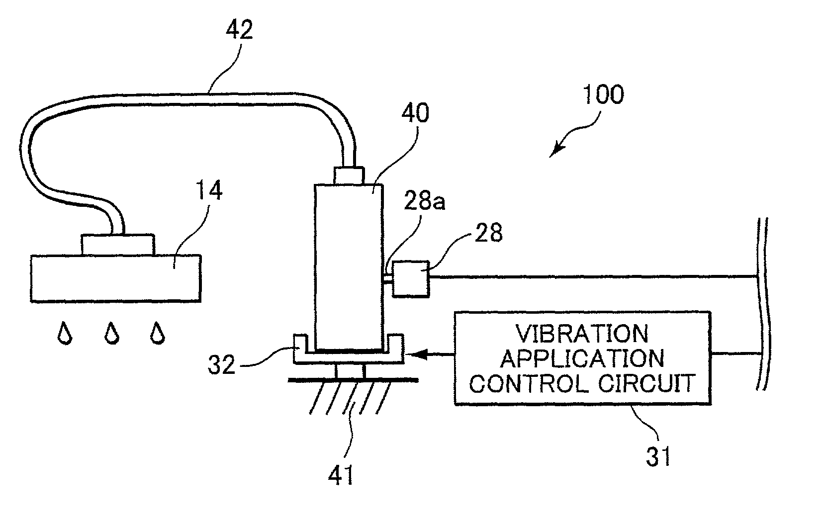
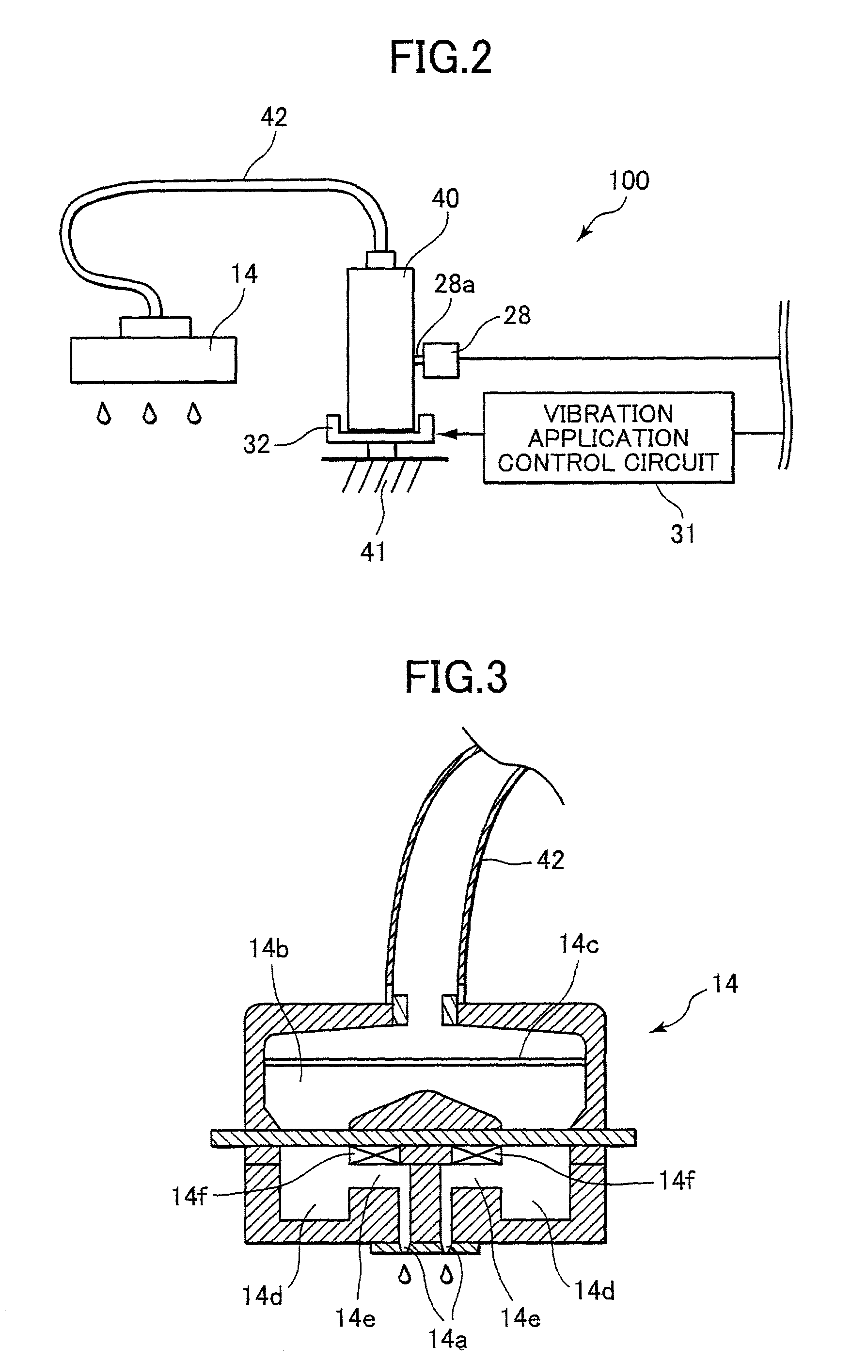
[0028] A carriage 6 is mounted on the linear scalar 5, and supports print heads 14 and drive circuit boards 8. Each drive circuit board 8 drives a corresponding print head 14 to eject one of four colors of ink: black, magenta, cyan, and yellow. An X-axis motor 7 is provided on a right end of the X-axis frame 4 for driving the carriage 6 to slidingly move reciprocally across the linear scalar 5 in the lengthwise direction of the linear scalar 5.

[0029] A Y-axis frame 9 is disposed on...

second embodiment

[0042] Next, a vibration application control routine B performed will be described while referring to the flowchart in FIG. 10. First, it is determined in S21 whether or not the print head 14 is presently being used to print. If not (S21:NO), then in S23 the light propagation sensor 34a detects a light propagation rate of the ink 51 inside the sub tank 50, and in S25 it is determined whether or not if the detected light propagation rate is greater than a predetermined threshold value. This determination can be made using a well-known dynamic light scattering method, such as Doppler scattered light analysis. If the detected light propagation rate is equal to or lower than the predetermined threshold value (S25:NO), then this means that pigments in the ink 51 have cohered or settled out, so that a vibration application routine is executed in S26. In this vibration application routine, first the CPU 20 transmits a vibration application command to the vibration application control circ...

fourth embodiment

[0054] Next, a vibration application control routine C performed will be described while referring to the flowchart in FIG. 16. First, in S31, the molecular-weight distribution detector 34c detects the molecular-weight distribution of the ink. Then, in S33, it is determined whether the detected molecular-weight distribution is greater than a predetermined threshold value. If not (S33:NO), this means that the molecular-weight distribution of the ink is normal. Then, the routine returns to S31.

[0055] On the other hand, if it is determined in S33 that the detected molecular-weight distribution is equal to or lower than the predetermined threshold value (S33:YES), this means that the molecular-weight distribution of the ink is not normal, so that a vibration application routine is executed in S35. In this vibration application routine, first the CPU 20 transmits a vibration application command to the vibration application control circuit 31. Then, the vibration application control circ...


PUM


Abstract

An ink tank 40 is placed on an ultrasonic vibrator 32. When a certain condition is established, such as when the print head 14 is exchanged, then the ultrasonic vibrator 32 generates ultrasonic vibration in ink stored in the ink tank 40. The ultrasonic vibration disperses cohered or settled-out pigments throughout the ink when a pigment-based ink is used, or breaks up any molecular binding to reduce the molecular-weight distribution when polymeric ink is used.

Description

[0001] 1. Field of the Invention[0002] The present invention relates to an inkjet device capable of preventing cohesion and sedimentation of ink in an ink reservoir.[0003] 2. Related Art[0004] There has been known an inkjet printer that includes an inkjet head formed with a plurality of nozzles through which ink droplets are ejected onto a recording medium to form images thereon. There are also provided various types of inks, including dye-based inks, pigment-based inks, and polymeric inks, that can be used in such an inkjet printer. Pigment-based inks have a problem in that the pigments in the ink can easily cohere with each other or settle out from the liquid base. Polymeric inks have a problem in that over time the molecular-weight distribution can increase because of molecular coupling. When these problems arise, printing results can be erratic and the ink nozzles can become clogged.[0005] In order to overcome these problems, there has been proposed to provide stirrer bares, suc...

Claims


Application Information

Patent Timeline
Patent Type & Authority Applications(United States)
IPC IPC(8): B41J2/04B41J2/175
CPCB41J2/04B41J2/175
Inventor ASANO, TAKESHI
Owner BROTHER KOGYO KK
Why Eureka
Try Eureka