String tensioning force controlling apparatus for a racket stringer

a string tensioning force and control apparatus technology, applied in the field of racket stringers, can solve the problems of large error, inability to micro-adjust the poundage of the tensioned string, and the sensor which generates the analog signal, such as the strain meter, to achieve the effect of reducing the risk of error

Inactive Publication Date: 2003-02-06
VAN DER POLS ERIK B
View PDF11 Cites 15 Cited by
  • Summary
  • Abstract
  • Description
  • Claims
  • Application Information

AI Technical Summary

Problems solved by technology

Even if, in accordance with the above arrangement, a heavy weight is used to tension the string, the operation by being a substantially manual one, still often results in great error.
Moreover, the weights gradationally vary from one another such that the poundage of the tensioned string cannot be micro-adjusted.
The sensor which generates the analog signal, such as the strain meter, is likely to produce error due to the change of environmental factors, such as temperature.
Such design can easily produce error of the value detected by the sensor.
This leads to error in the output analog signal generated by the sensor.
Thus, the detection measurement provided by the output analog signal contains considerable error so that the pulling tension exerted onto the racket string by the prior art string pulling mechanism cannot be accurately controlled.
Another disadvantage to this prior art racket stringer is that the wiring from the sensor moves with the string pulling head while tensioning the string.
This can result in premature wear to the sensor wires and eventually they will need to be replaced.
The tension in the string is controlled manually by observing the LED display and is very difficult to control to achieve the desired tension in the string.
Due to variations in the spring rate of different springs, the biasing spring is rarely matched perfectly to the discrete indicators on the sensor member, resulting in inaccurate tension display.
This makes controlling the tension applied to the string and achieving the desired tension in the string difficult, if not impossible.

Method used


Image

  • String tensioning force controlling apparatus for a racket stringer
  • String tensioning force controlling apparatus for a racket stringer
  • String tensioning force controlling apparatus for a racket stringer

Examples


Embodiment Construction

[0025] In the following description, like reference characters designate like or corresponding parts throughout the several views of the drawings. Also in the following description, it is to be understood that such terms as "forward", "rearward", "left", "right", "upwardly", "downwardly", and the like are words of convenience and are not to be construed as limiting terms.

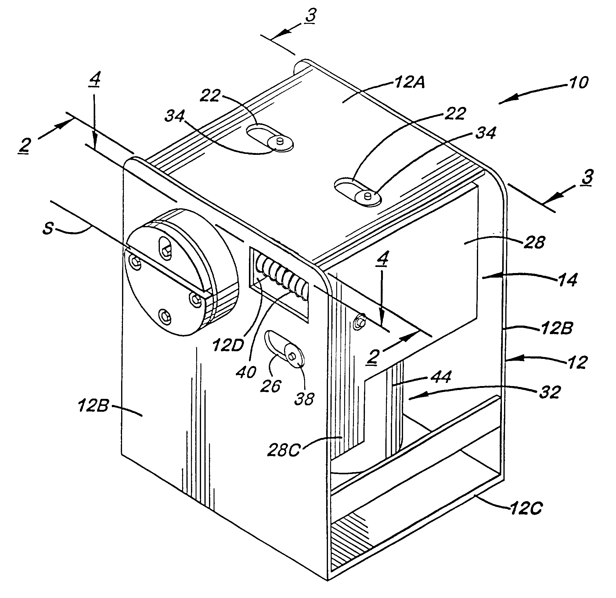
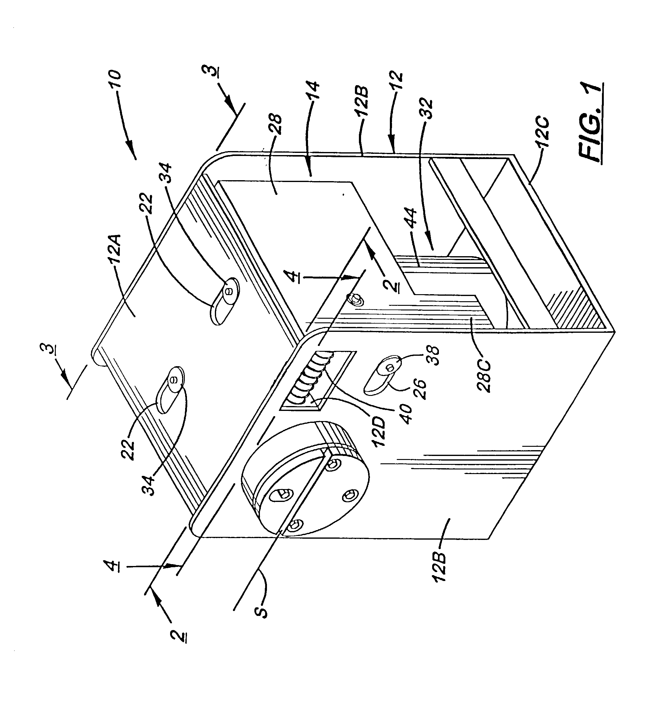
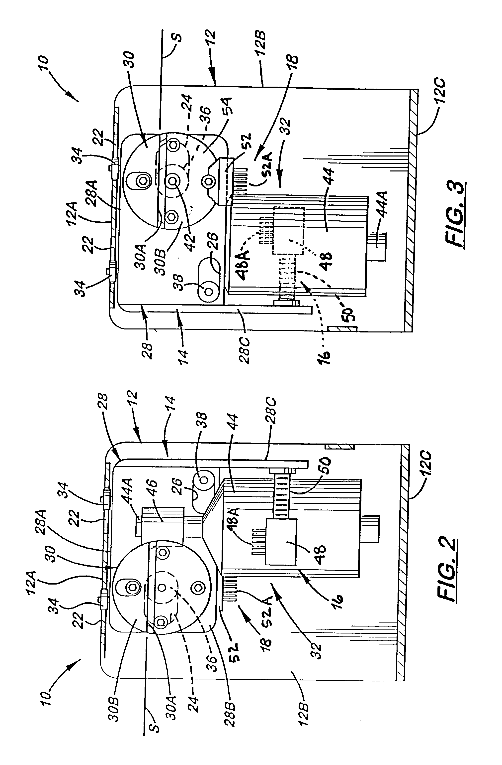
[0026] Referring to the drawings and particularly to FIGS. 1-5, there is illustrated a first embodiment of a string tensioning force controlling apparatus, generally designated 10, of the present invention, for use in an otherwise conventional racket stringer. The string tensioning force controlling apparatus 10 of the present invention basically includes a base seat or housing 12 which is stationarily positioned, a string pulling mechanism 14 mounted to the base housing 12, first and second encoders 16,18 which are associated with the string pulling mechanism 14 and base housing 12, and a central processing unit 20...


PUM


Abstract

A string tensioning force controlling apparatus for a racket stringer includes a string pulling mechanism having a support housing, a string pulling head movably supported by the support housing for engaging a string, and a drive arrangement drivingly coupled to the string pulling head. The apparatus also includes an encoder disposed adjacent to the string pulling mechanism for sensing displacement of the string pulling head relative to the support housing and generating a digital output signal representative thereof, and a central processing unit for receiving the digital output signal and in response thereto controlling operation of the drive arrangement to move the string pulling head such that a desired tensioning force is accurately applied to the string so as to produce a tensioned string.

Description

[0001] 1. Field of the Invention[0002] The present invention generally relates to a racket stringer and, more particularly, is concerned with a string tensioning force controlling apparatus for a racket stringer.[0003] 2. Description of the Prior Art[0004] A traditional racket stringer has a rock arm onto which weights are manually added. By means of different weights, the rock arm is turned to create different torque for driving a string pulling head to pull and tension a racket string. The racket string is tensioned by different poundage.[0005] Even if, in accordance with the above arrangement, a heavy weight is used to tension the string, the operation by being a substantially manual one, still often results in great error. Moreover, the weights gradationally vary from one another such that the poundage of the tensioned string cannot be micro-adjusted.[0006] One prior art racket stringer employs a motor for driving a gear set to create torque for driving the string pulling head a...

Claims


Application Information

Patent Timeline
Patent Type & Authority Applications(United States)
IPC IPC(8): A63B51/14
CPCA63B51/14
Inventor VAN DER POLS, ERIK B.
Owner VAN DER POLS ERIK B
Why Eureka
Try Eureka