Socket contact and socket connector

a socket connector and socket technology, applied in the direction of coupling contact members, coupling device connections, securing/insulating coupling contact members, etc., can solve the problems of unintentionally and undesired removal of the insulating housing, and the insufficient length of the conta

Inactive Publication Date: 2003-12-25
JST MFG CO LTD
View PDF11 Cites 72 Cited by
  • Summary
  • Abstract
  • Description
  • Claims
  • Application Information

AI Technical Summary

Problems solved by technology

However, such a lance is not necessarily large enough to ensure a firm retention of the contact, particularly if connectors and their contacts are made smaller and smaller.
If a stretching, wrenching or the like external force is imparted to the wire end secured in the contact, then it will likely be unintentionally and undesirably removed from the insulating housing.

Method used


Image

  • Socket contact and socket connector
  • Socket contact and socket connector
  • Socket contact and socket connector

Examples


Embodiment Construction

[0020] Now some embodiments of the present invention will be described in detail, referring to the drawings.

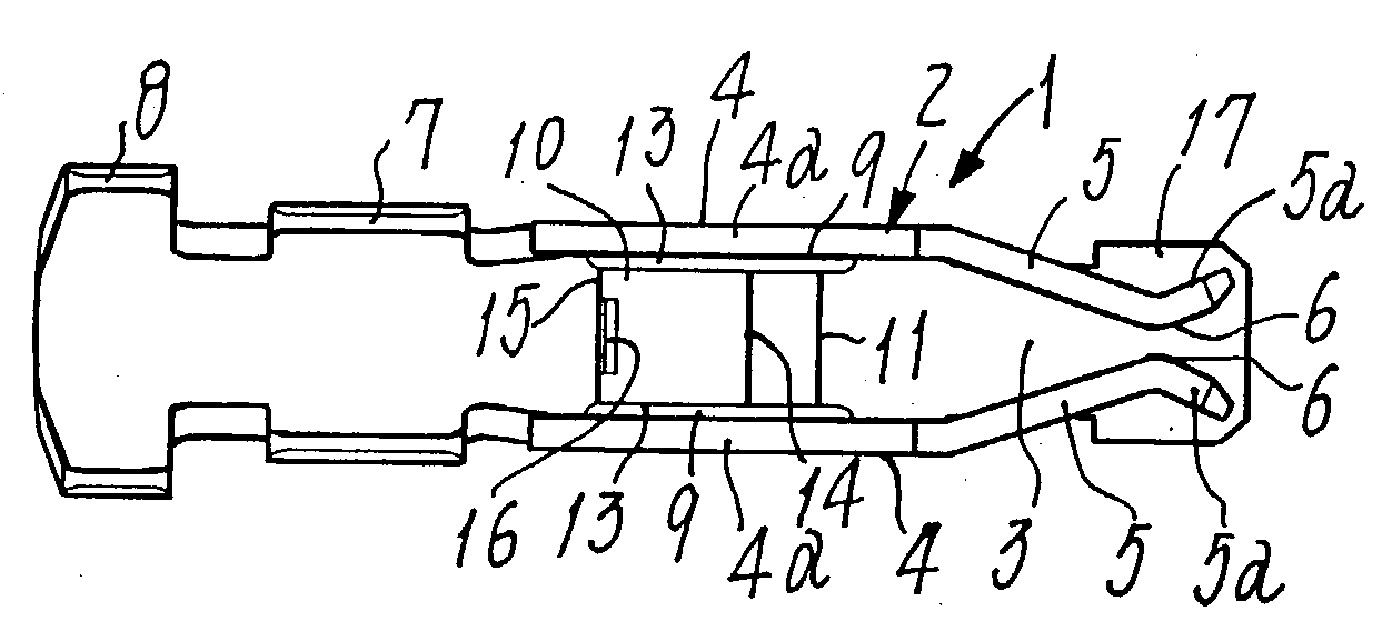
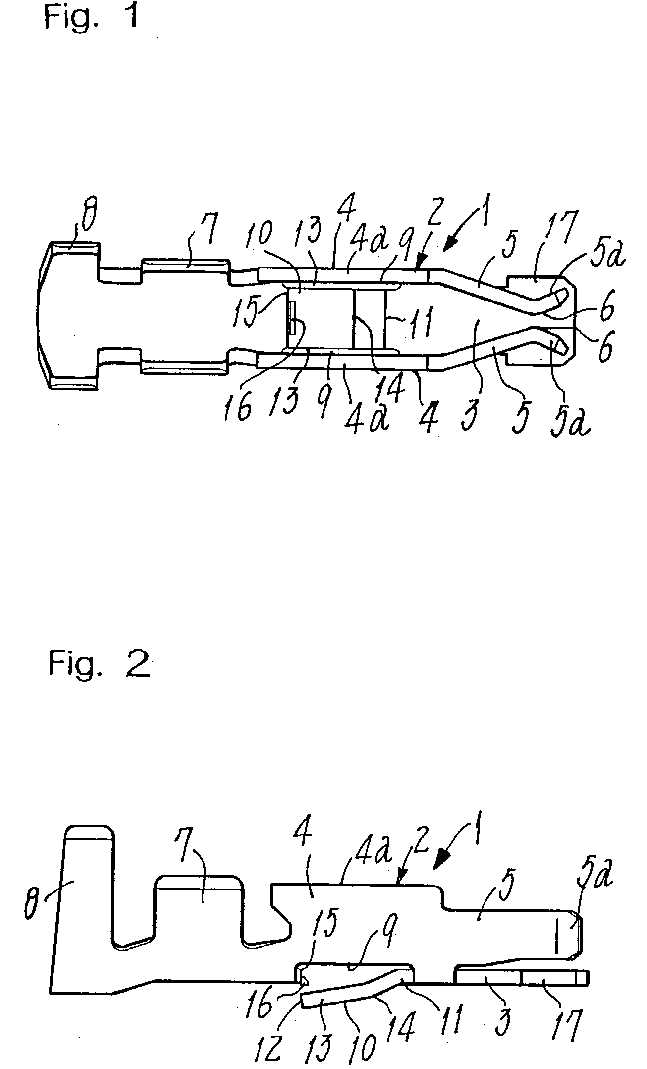
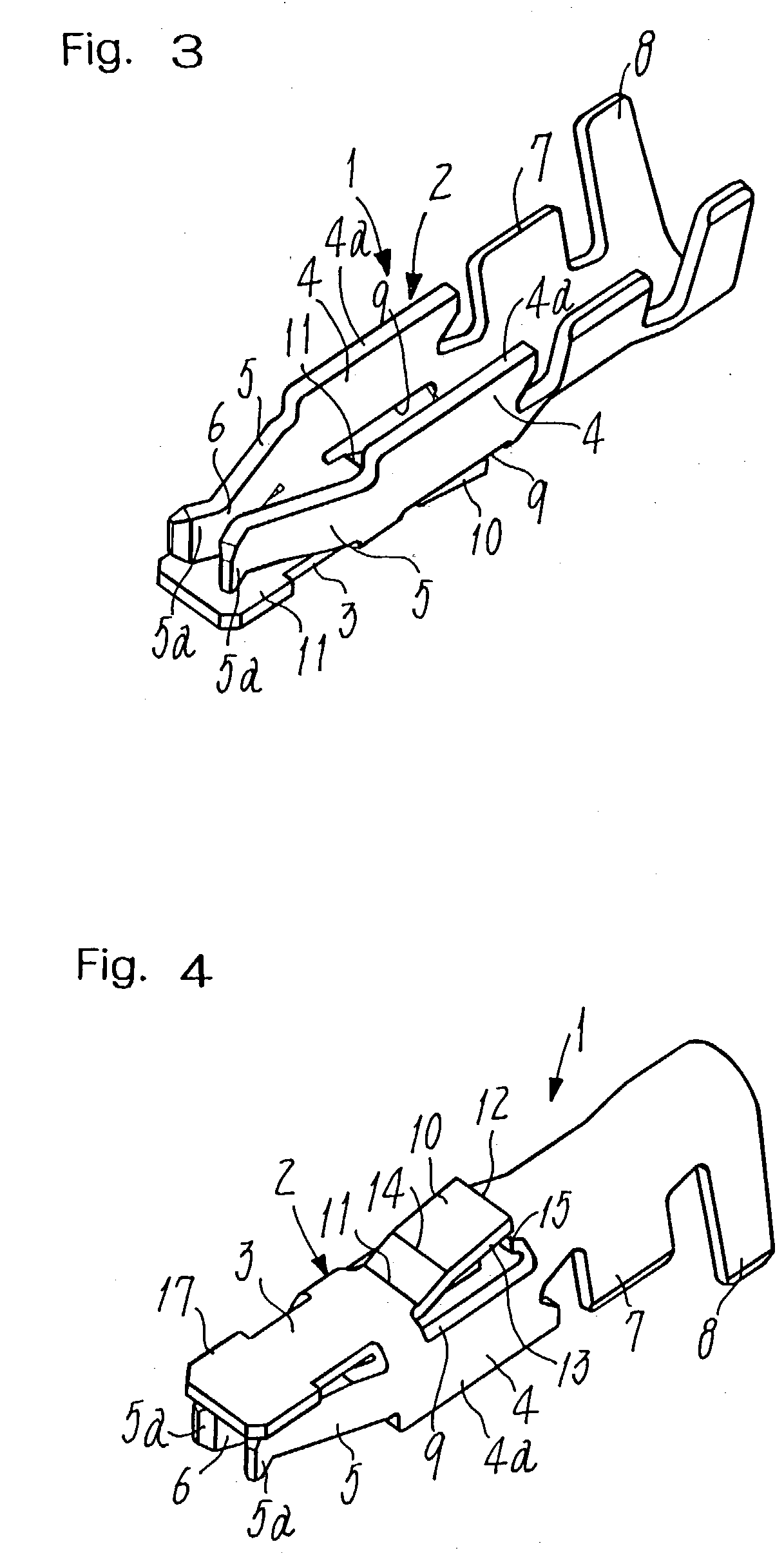
[0021] A socket contact 1 of the invention illustrated in FIGS. 1 to 4 is a conductive piece made by pressing a thin metal plate such as a phosphor bronze plate. A body 2 of this contact is composed of a bottom 3 and a pair of lateral walls 4 bent upwards. These walls 4 continue from a middle region of the bottom 3 so as to render the contact body 2 generally U-shaped in cross section. A pair of resilient contact leaves 5 protrudes inwards from the inner ends of respective lateral walls 4. These contact leaves 5 are slanted to become closer and closer to each other as they extend inwards to terminate short of the inner end of bottom 3. However, the inner end portions 5a of such resilient leaves 5 are then bent sideways and away from each other to pro-vide contact surfaces 6. A pin contact (not shown) of a mating connector will fit in between the contact surfaces 6 of these lea...


PUM


Abstract

A socket connector (35) has a socket contact (1) installed in it, the contact being for connection with a wire end (20) in isolated compartment (26) of an insulating housing (25), the contact having a body (2) U-shaped in cross section composed of bent-up lateral walls (4) and a bottom (3). A lance (10) formed by punching the bottom protrudes outwards to be of the same width as a transverse width of the bottom and have two bent portions. One of the bent portions is located at a basal end (11) of the lance, and the other at a middle region (14) of the lance, thereby affording improved rigidity and resiliency to the lance. The bottom (3) has a broadened inner end (17) of the same width as a transverse width of contact body (2), so that the lance is of an improved rigidity and resiliency to be firmly retained in a connector housing not to slip off, even if made smaller in size.

Description

[0001] The present invention relates to a socket contact and a socket connector that are relatively smaller in size adapted for use where high voltages are applied to them.PRIOR ART[0002] Back-lights are used as the light sources for liquid crystal displays incorporated in personal computers. Power source circuits for such back-lights are connected to the outside through electric connectors, that are desirably smaller-sized and resistant to high voltages. Some connectors of this kind are known in the art (see for example the Japanese Patent Laying-Open Gazettes No. 10-125384 and No. 2000-252005). Socket contacts secured on wire ends are isolated from each other, since they are held in respective compartments formed in an insulating housing. Each socket contact has a bottom, and whose portion provides a lance pressed outwards from it so as to engage with a slot or lug formed in the insulated housing, thus retaining the contact therein.[0003] However, such a lance is not necessarily l...

Claims


Application Information

Patent Timeline
Patent Type & Authority Applications(United States)
IPC IPC(8): H01R13/11H01R13/428H01R13/432
CPCH01R13/432H01R13/11
Inventor KURODA, KEIJIARAMOTO, KIYOSHIIWASHITA, KOJI
Owner JST MFG CO LTD
Why Eureka
Try Eureka