
Press-formed keyway for headrest mounting tube

a technology of mounting tube and keyhole, which is applied in the field of headrest mounting tube, can solve the problems of operator injuries, jagged and sharp edges on the sides of the slot, and the force required to do this is usually too much for the punch

Inactive Publication Date: 2004-02-05
BEND ALL AUTOMOTIVE
View PDF0 Cites 20 Cited by
  • Summary
  • Abstract
  • Description
  • Claims
  • Application Information

AI Technical Summary

Problems solved by technology

Attempts have been made to remove the metal, to form the slot, by means of a tool that is pushed into the tube axially, from the end of the tube, but the force necessary to do this has usually been too much for the punch, which has to be small enough to fit inside the tube.
Making the slot by shearing the metal, especially from inside the tube, can leave the sides of the slot jagged and sharp-edged.
This can cause injuries to the operators.
When the slot has sharp edges, plastic material might be shaved from the key, and the resulting looseness might lead to a rattle.
But such operations as these are generally quite expensive, not least because transfer of the tube to another processing facility would be required.

Method used


Image

  • Press-formed keyway for headrest mounting tube
  • Press-formed keyway for headrest mounting tube
  • Press-formed keyway for headrest mounting tube

Examples


Embodiment Construction

[0019] By way of further explanation of the invention, exemplary embodiments of the invention will now be described with reference to the accompanying drawings, in which:

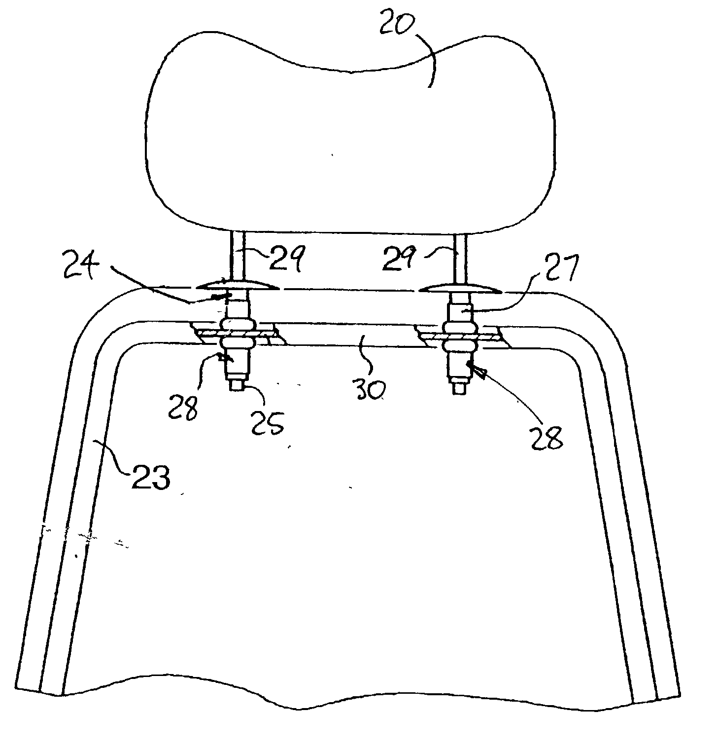
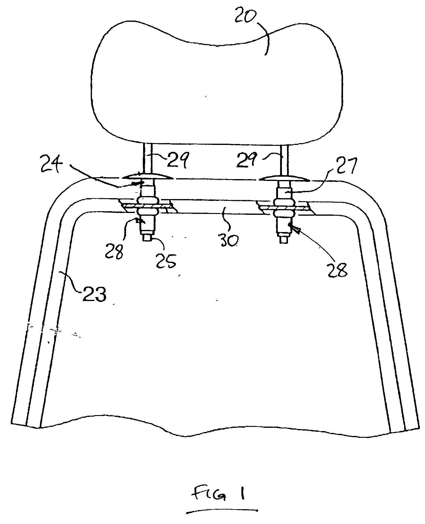
[0020] FIG. 1 shows part of an automotive seat, with a headrest. The headrest-mounting-tubes in the seatframe have keyway-pockets which incorporate the invention.

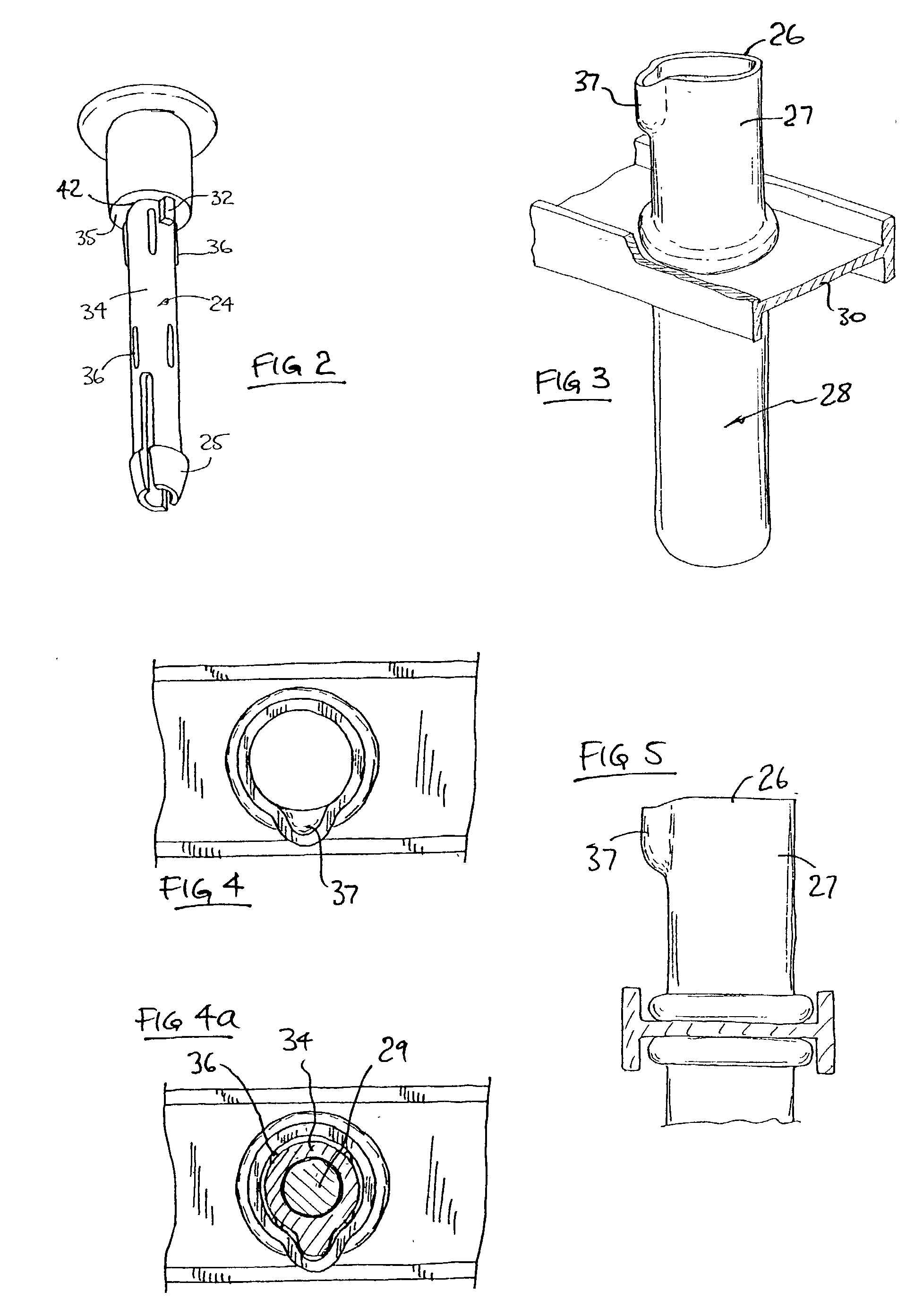
[0021] FIG. 2 is a pictorial view of a sleeve, being a component of a headrest-post of the seat of FIG. 1.

[0022] FIG. 3 is a perspective view of a headrest-mounting-post of the seat of FIG. 1, which includes a keyway-pocket.

[0023] FIG. 4 is a plan view of the headrest-mounting-tube of FIG. 3.

[0024] FIG. 4a is the same view as FIG. 4, but includes the headrest-post sleeve of FIG. 2.

[0025] FIG. 5 is a side view of the headrest-mounting-tube of FIG. 3.

[0026] FIG. 6 is a diagrammatic representation of a punch and die set, as used for forming the keyway-pocket of FIG. 3.

[0027] FIG. 7 is a plan view of the punch of FIG. 6.

[0028] The apparatuses shown in the accom...


PUM


Abstract

Headrest-mounting-tubes are attached into the seatframe of an automotive seat. Headrest-posts engage the mounting-tubes, and support the headrest. The headrest-posts need to be orientated correctly, and so have a key that engages a keyway in the mounting-tube. The keyway is formed as a keyway-pocket, being punched from the open end of the tube. Preferably, the keyway-pocket is punched after the mounting-tube has been attached into the seatframe.

Description

BACKGROUND TO THE INVENTION[0001] This invention relates to headrest-mounting-tubes, for use in connection with automotive seats. Such tubes are shown, for example, in patent publication U.S. Pat. No. 6,035,516 (Petersen, March 2000).[0002] Headrests for vehicle seats have two posts protruding downwards, and these posts engage in headrest-mounting-tubes that are attached to the top-rail of the seatframe. In the past, it has been the common practice to attach the headrest-mounting-tubes to the top-rail by welding.[0003] However, the recent trend is to attach the tubes to the top-rail by a cold-forming method. The top-rail of the seatframe is mounted in a die, and the headrest-mounting-tube is subjected to a punching force exerted in the axial sense relative to the tube, whereby the metal of the tube engages with the top-rail, and crumples and folds, in such manner as to leave the tube firmly secured to the top-rail, as shown in the said U.S. Pat. No. 6,035,516, this manner of securem...

Claims


Application Information

Patent Timeline
Patent Type & Authority Applications(United States)
IPC IPC(8): A47C7/38B60N2/48
CPCB60N2/48B60N2/80
Inventor KEY, ARTHUR A.THOMAS, JEFFREY JOHNGLEISER, MATTHEW RICHARDNAPOLITANO, ALFRED D. JR.
Owner BEND ALL AUTOMOTIVE
Learn More