Floor sweeper having a viewable receptacle

a floor sweeper and receptacle technology, applied in the field of floor sweepers, can solve the problems of operator's inability to ascertain the contents of interest, device suffers from at least one usability flaw, and operator's inability to know if the brush roller is jammed or no

Inactive Publication Date: 2004-07-29
WILDWOOD INDS
View PDF5 Cites 115 Cited by
  • Summary
  • Abstract
  • Description
  • Claims
  • Application Information

AI Technical Summary

Benefits of technology

The invention is a floor sweeper that has a handle, a base, wheels, a roller brush, and a bottom receptacle. The improvement is that the top portion of the sweeper is made of transparent material. This allows the user to see what is being captured by the sweeper and the movement of the brush rollers during operation.

Problems solved by technology

The technical problem addressed in this patent text relates to improving non-motorized floor sweppers by allowing users to easily see what they collect while using them. Previous versions had limited visibility due to design factors, making it hard for operators to determine whether their machines were working properly or needed maintenance.

Method used


Image

  • Floor sweeper having a viewable receptacle
  • Floor sweeper having a viewable receptacle

Examples


Embodiment Construction

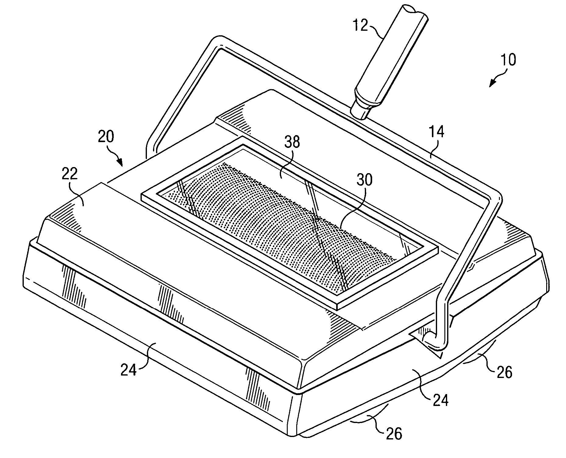
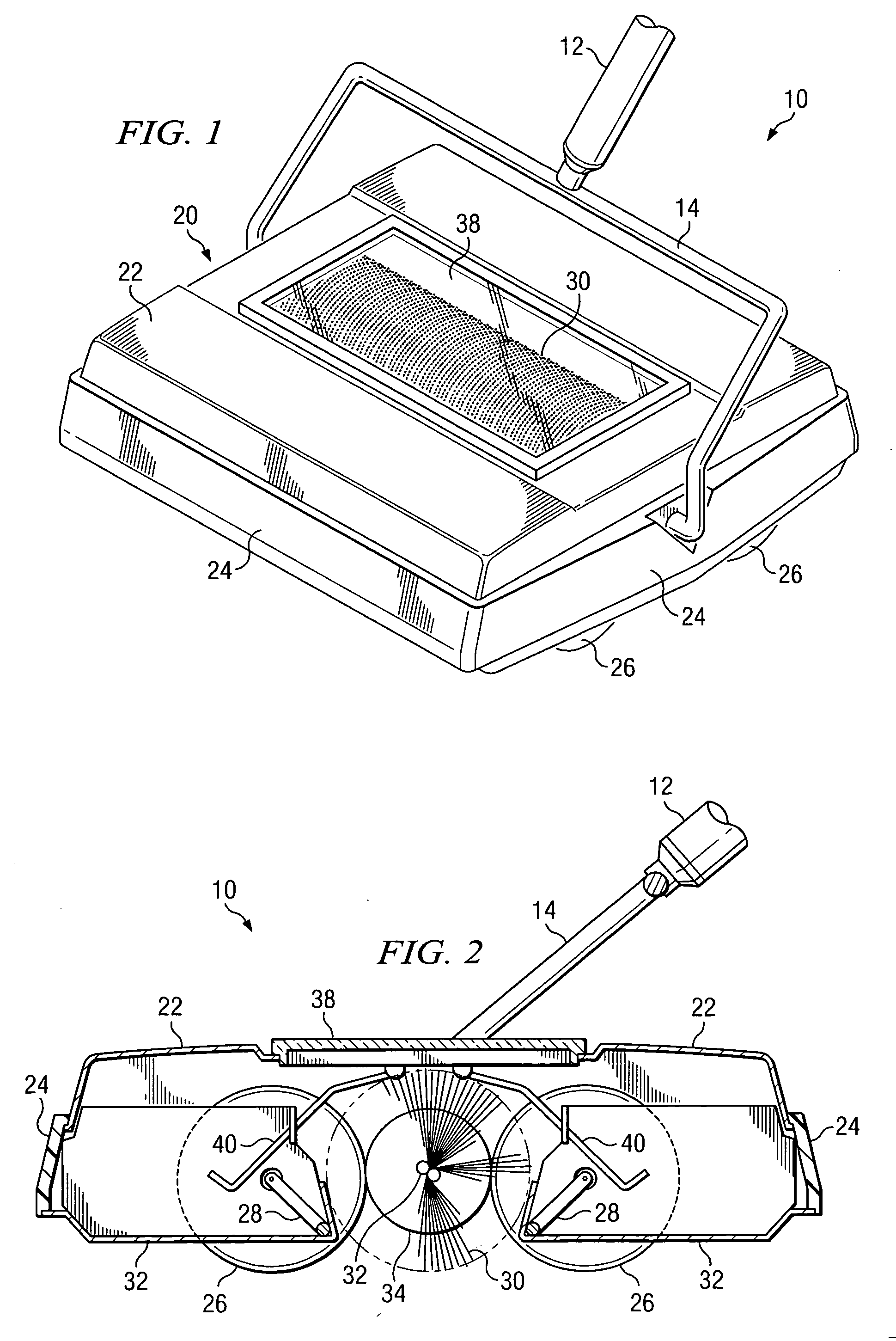
[0014] The sweeper according to the present invention will be described herein by reference to the accompanying drawings wherein FIGS. 1 and 2 illustrate one preferred embodiment of the present invention, in which like parts are shown by corresponding reference numerals throughout.

[0015] As can be seen in FIG. 1, the sweeper 10 of the instant invention is generally comprised of a handle 12 pivotally attached by a pivotable arm 14 to a body or base portion 20, such that the handle 12 can be pivoted downward to a horizontal position even with the top of the body to allow a variety of handle positions, such that the sweeper 10 can be maneuvered into horizontal spaces, such as under furniture. The base portion 20 is more specifically comprised of a horizontal top 22 and four vertical sides 24 attached to the top, such that a box-like structure is formed having an opened bottom (as can be seen in FIG. 2).

[0016] Referring to FIG. 2, at least two sets of wheels 26 are attached to the botto...


PUM


Abstract

A floor sweeper for the collection of debris from a surface which comprises a handle pivotatably attached to a body have top and side portions and a open bottom containing at least two sets of wheels, at least one roller brush and one or more collection receptacles. At least segment of the top portion of the body contains is formed of a transparent material, such that a window or similar structure is provided for the sweeper user to observe the function of the sweeper or the amount and type of debris accumulated therein.

Description


Claims


Application Information

Patent Timeline
Owner WILDWOOD INDS
Why Eureka
Try Eureka