Quick-pour can

Inactive Publication Date: 2004-07-29
HECK JONATHAN ANDREW
View PDF12 Cites 33 Cited by
  • Summary
  • Abstract
  • Description
  • Claims
  • Application Information

AI Technical Summary

Problems solved by technology

Although the design of such a pouring mechanism has changed, the problems inherent in a single opening persist.
In any single opening container, for fluid to exit, air must enter and displace the fluid; this causes a slow and uneven stream of liquid that undulates as it pours.
Besides the mere aesthetic issues that this creates, there are many functional problems that result from an uneven flow of fluids.
The liquid pours out of the container slowly, making it nearly impossible to quickly imbibe the fluids directly from the can.
In some situations, it is desirable to be able to quickly drink the contents of a can; however, this feat is extremely difficult because of the slow, uneven flow and the problems that result from it.
As well, an undulating flow makes it very difficult to pour the contents of the can into a small opening or container without spilling.
Another problem in many prior art cans is the inability to pour the entire contents of the can, leaving a few last drops once consumption of the beverage is complete.
Besides being wasteful, these unconsumed remnants can be a nuisance when a person partakes in recycling the cans.
Prior art has to this point been unable to solve the problem of excess foam or "head".
Much of this foam is caused by the uneven pour of fluids from a single-opening beverage container into a glass.
This foam makes it difficult to quickly consume the beverage directly from the can.
Although "widemouth" cans have attempted to solve this problem and others, they still have only one opening and therefore are subject to the same problems.
Although this solves the problem of an uneven pour, it creates many new and undesirable consequences.
Further, this design requires a person to open two separate apertures, the second one being in an awkward position, which can easily lead to spillage.

Method used


Image

  • Quick-pour can
  • Quick-pour can
  • Quick-pour can

Examples


Embodiment Construction

[0046] 1. Detailed Description of the Preferred Embodiment Figures

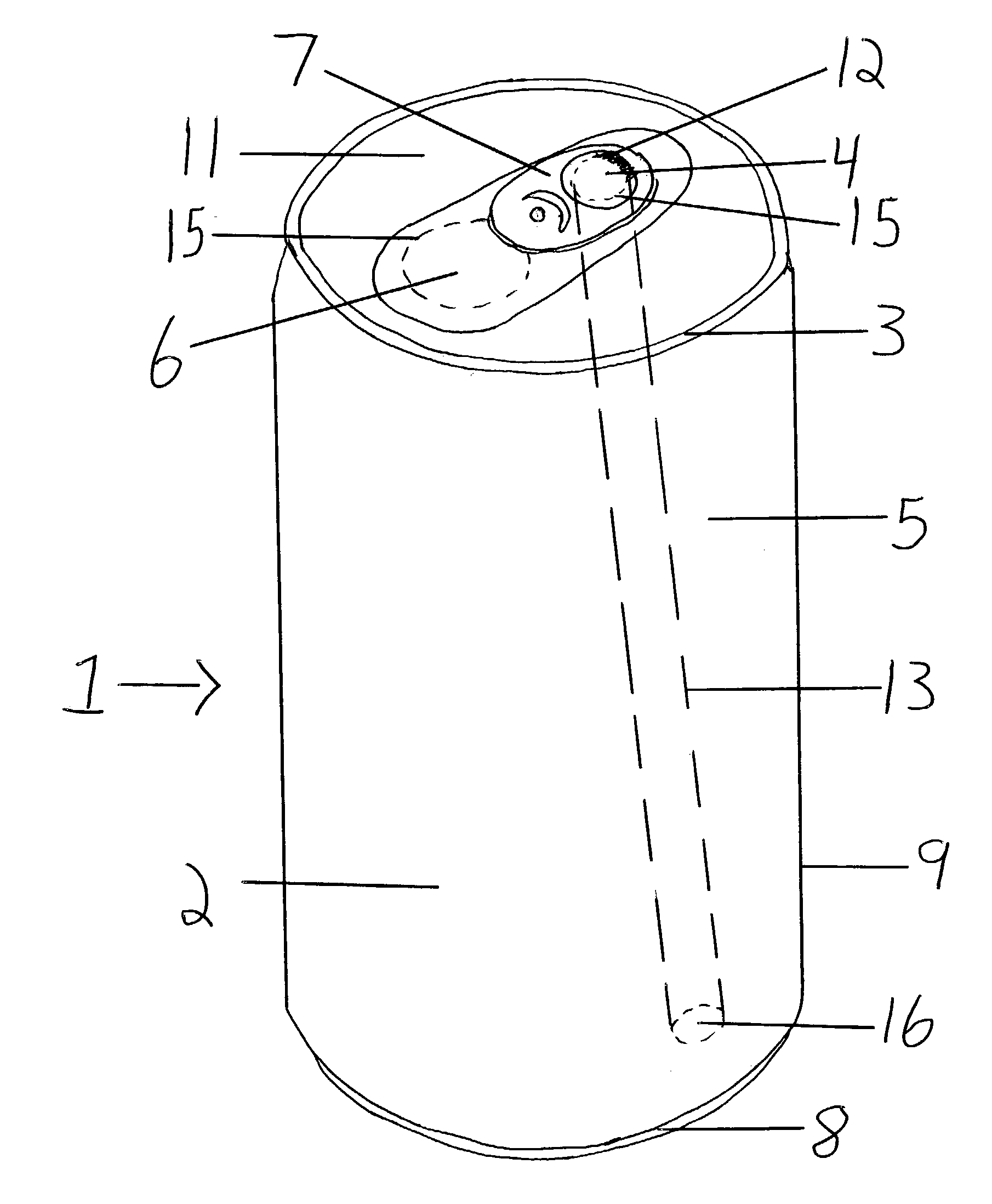
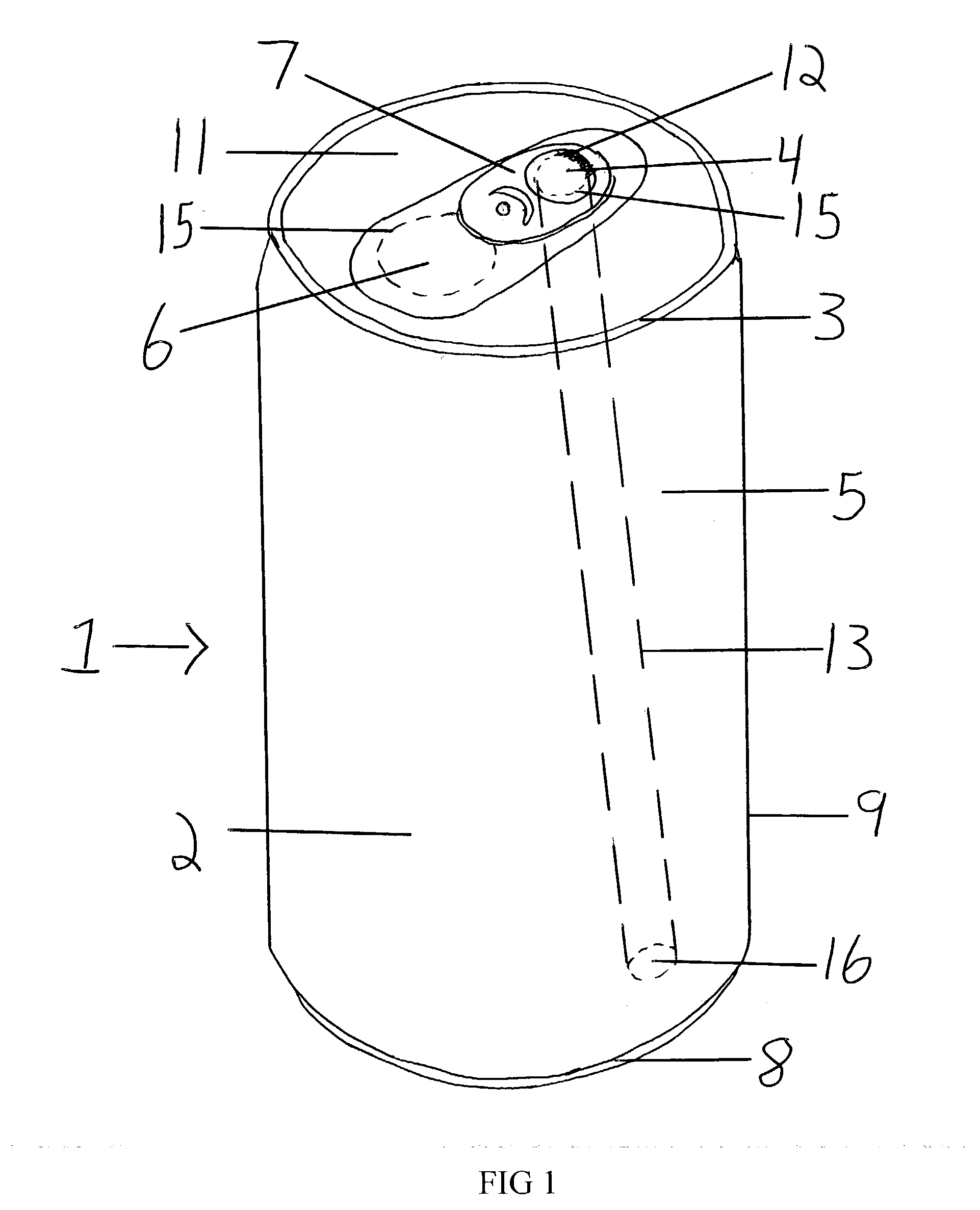
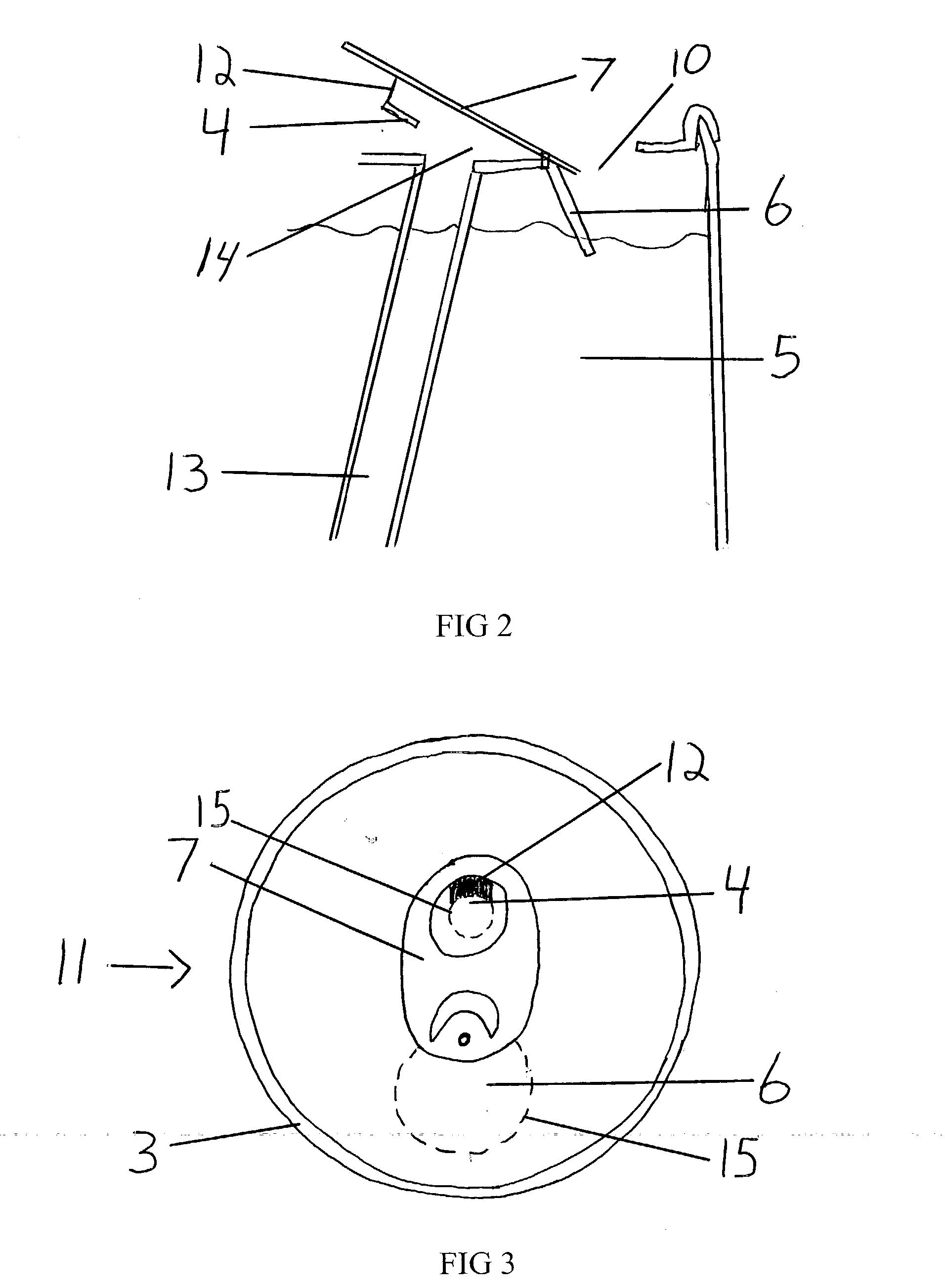
[0047] A typical embodiment of the present invention is illustrated in FIGS. 1 through 4. Referring to FIGS. 1 and 3, a dual-aperture beverage container 1 and a container top 11 are shown respectively. In the main embodiment, a container 2 consists of a container sidewall 9 that wraps around to form a hollow cylinder. The container sidewall 9 is made of metal and is effectively closed on both open ends so that it can completely seal the beverage inside. On top of the container sidewall 9 is connected the container top 11, while the bottom is sealed off with a container bottom 8. Like the container sidewall 9, the container top 11 and container bottom 8 are both made of metal. The container top 11 contains a pouring scored section 6, a tab 7, a venting scored portion 4, a container rim 3, a connecting metal 12, and a hollow venting tube 13. The container rim 3 is simply the circumference of the container top 11, securi...


PUM


Abstract

A dual aperture beverage can (1) consisting of a venting scored section (4) and a pouring scored section (6) on the container top (11). The container (2) is comprised of a container sidewall (9), a container top (11), and a container bottom (8). A tab (7) is employed to open both the venting scored section (4) and the pouring scored section (6), such that their respective apertures are revealed. The pouring aperture (10) is of the traditional style common in the beverage can industry, while the venting aperture (14) leads to a hollow venting tube (13). The hollow venting tube (13) leads to near the bottom of the container. It is this manner, that air can enter the venting aperture (14) and displace the liquid from the bottom of the can while the fluid flows quickly and evenly out the pouring aperture (10).

Description

[0001] 1. Field of Invention[0002] This invention relates to beverage cans, specifically to the manually-operated mechanism that allows for the flow of fluids.[0003] 2. Description of Prior Art[0004] Previously, beverage cans have employed a simple single opening aperture to allow for the fluids therein to be poured. Although the design of such a pouring mechanism has changed, the problems inherent in a single opening persist. In any single opening container, for fluid to exit, air must enter and displace the fluid; this causes a slow and uneven stream of liquid that undulates as it pours. Besides the mere aesthetic issues that this creates, there are many functional problems that result from an uneven flow of fluids. The liquid pours out of the container slowly, making it nearly impossible to quickly imbibe the fluids directly from the can. In some situations, it is desirable to be able to quickly drink the contents of a can; however, this feat is extremely difficult because of the...

Claims


Application Information

Patent Timeline
IPC IPC(8): B65D8/02B65D17/34
CPCB65D17/165B65D2517/0094B65D2517/0061B65D2517/0014B65D17/4012
Inventor HECK, JONATHAN ANDREW
Owner HECK JONATHAN ANDREW
Why Eureka
Try Eureka