Self-propelled cleaning device and charger using the same

a cleaning device and self-propelled technology, applied in the direction of electric equipment installation, manufacturing tools, instruments, etc., can solve the problems of difficult to completely automate the cleaning device, corners of a room, and left unsucked dus

Inactive Publication Date: 2004-12-23
HITACHI LTD +1
View PDF1 Cites 187 Cited by
  • Summary
  • Abstract
  • Description
  • Claims
  • Application Information

AI Technical Summary

Problems solved by technology

The free running electric cleaning device described in Patent Document 1 does not have a means from detecting the projection amount of a suction body and a means for controlling the suction body on the basis of the position relationship between a wall and the cleaning device body, so that there is the possibility that in the corners of a room, there may be left unsucked dust.
Therefore, in a self-propelled cleaning device whose capacity is limited, dust must be disposed frequently, so that it is difficult to completely automat e the cleaning device.
Furthermore, in the self-propelled cleaning device described in Patent Document 3, only an obstacle in front of the self-propelled cleaning device can be detected, so that to move backward, the direction must be changed.

Method used


Image

  • Self-propelled cleaning device and charger using the same
  • Self-propelled cleaning device and charger using the same
  • Self-propelled cleaning device and charger using the same

Examples


Embodiment Construction

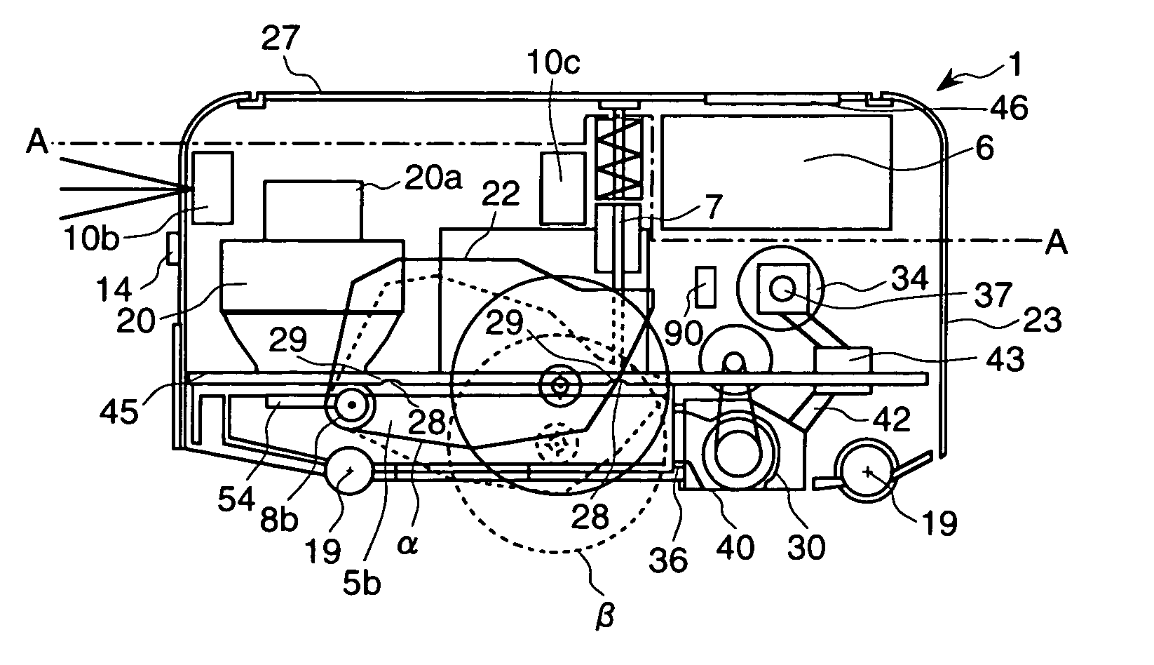
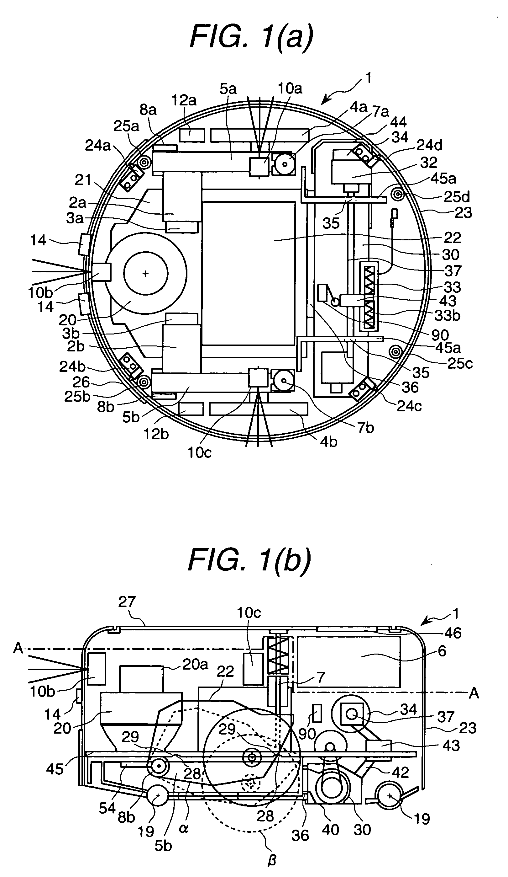
[0029] An embodiment of the self-propelled cleaning device system relating to the present invention will be explained with reference to FIGS. 1 to 8. The self-propelled cleaning device system has a cleaning device 1 freely running and cleaning dust and a charger 200 for supplying power to a storage battery 22 possessed by the cleaning device 1. FIG. 1 shows a cross sectional view of the self-propelled cleaning device 1. FIG. 1(a) is a cross sectional view along the line A-A shown in FIG. 1(b) and FIG. 1(b) is a longitudinal cross sectional view. The moving direction of the cleaning device 1 is the leftward direction of FIG. 1.

[0030] The structure of the self-propelled cleaning device 1 is formed in an almost cylindrical shape by a top cover 27 and a side cover 23. On both sides of the lower part in the cleaning device 1, a pair of drive wheels 4a and 4b for moving are mounted. The drive wheels 4a and 4b are individually driven by motors 2a and 2b mounted on the base. Speed reducers ...


PUM


Abstract

A self-propelled cleaning device having a cylindrical side cover has a suction body capable of moving transversely to the forward direction. The side cover is held by a base via a suspension. When cleaning corners of a room, the suction body moves by a wall and as the suction body moves to a corner, the movement amount of the suction body is changed. When an obstacle touches the cleaning device, the side cover moves, and the article touches a side cover switch, and the direction of the article is detected.

Description

[0001] 1. Field of the Invention[0002] The present invention relates to an electric cleaning device and a charger used for it and more particularly to a self-propelled cleaning device automatically movable and a charger used for it.[0003] 2. Prior Art[0004] An example of a conventional free-running electric cleaning device is described in Patent Document 1 (Japanese Patent Application Laid-Open Announcement 2002-532177). The electric cleaning device described in this patent application has a body provided with each support wheel, a drive means for driving wheels of the electric cleaning device so as to move a cleaning surface in the forward direction, a dust separator, and a fan for pulling air into the dust separator. And, to enable cleaning in contact with a wall, a head of the cleaning device is mounted so as to cross the forward direction and is projected at least on one side of the body. When there is an obstacle found, the projected head can be pulled into the body.[0005] Anot...

Claims


Application Information

Patent Timeline
Patent Type & Authority Applications(United States)
IPC IPC(8): A47L5/00A47L9/28A47L9/00A47L9/02A47L9/10B25J11/00G03G15/00G05D1/02
CPCA47L5/28A47L9/00A47L9/009A47L9/02A47L9/106A47L9/2805A47L9/2821A47L9/2852A47L9/2857A47L9/2873A47L9/2889A47L9/2894A47L2201/022A47L2201/04
Inventor ARAI, YUTAKAHOSODA, YUUJIEGAWA, SAKUSADAMORI, HIROYUKITANAKA, HIROFUMIYAMAMOTO, WATARUTAJIMA, TAIJIHATTORI, MAKOTO
Owner HITACHI LTD
Why Eureka
Try Eureka