Knitting machine

a knitting machine and pattern disk technology, applied in the field of knitting machines, can solve the problems of limited space that is available for the guide, high cost, and inability to repeat long repeats with the pattern disk

Inactive Publication Date: 2004-12-30
KARL MAYER TEXTILMASCHFAB GMBH
View PDF4 Cites 8 Cited by
  • Summary
  • Abstract
  • Description
  • Claims
  • Application Information

AI Technical Summary

Benefits of technology

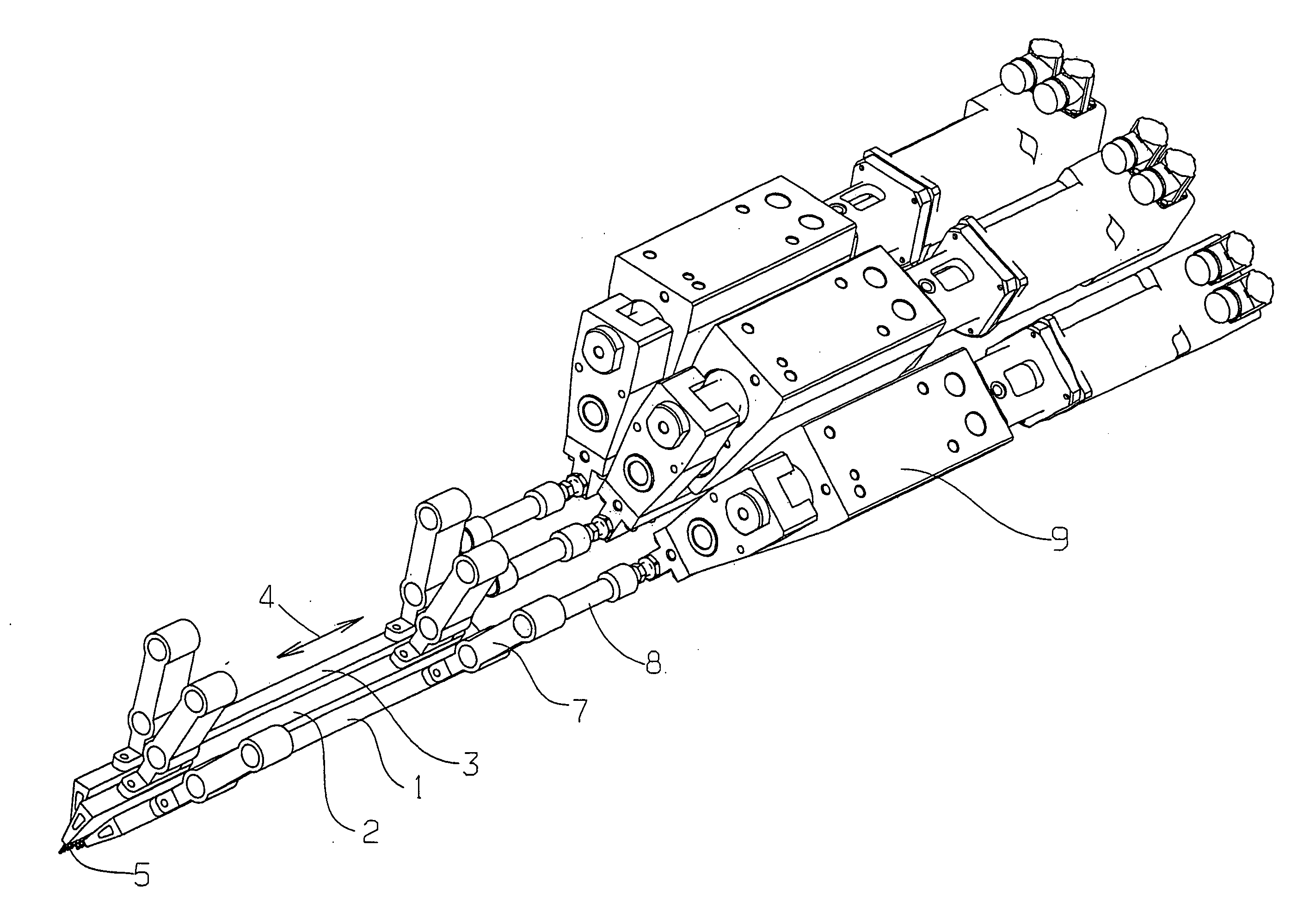
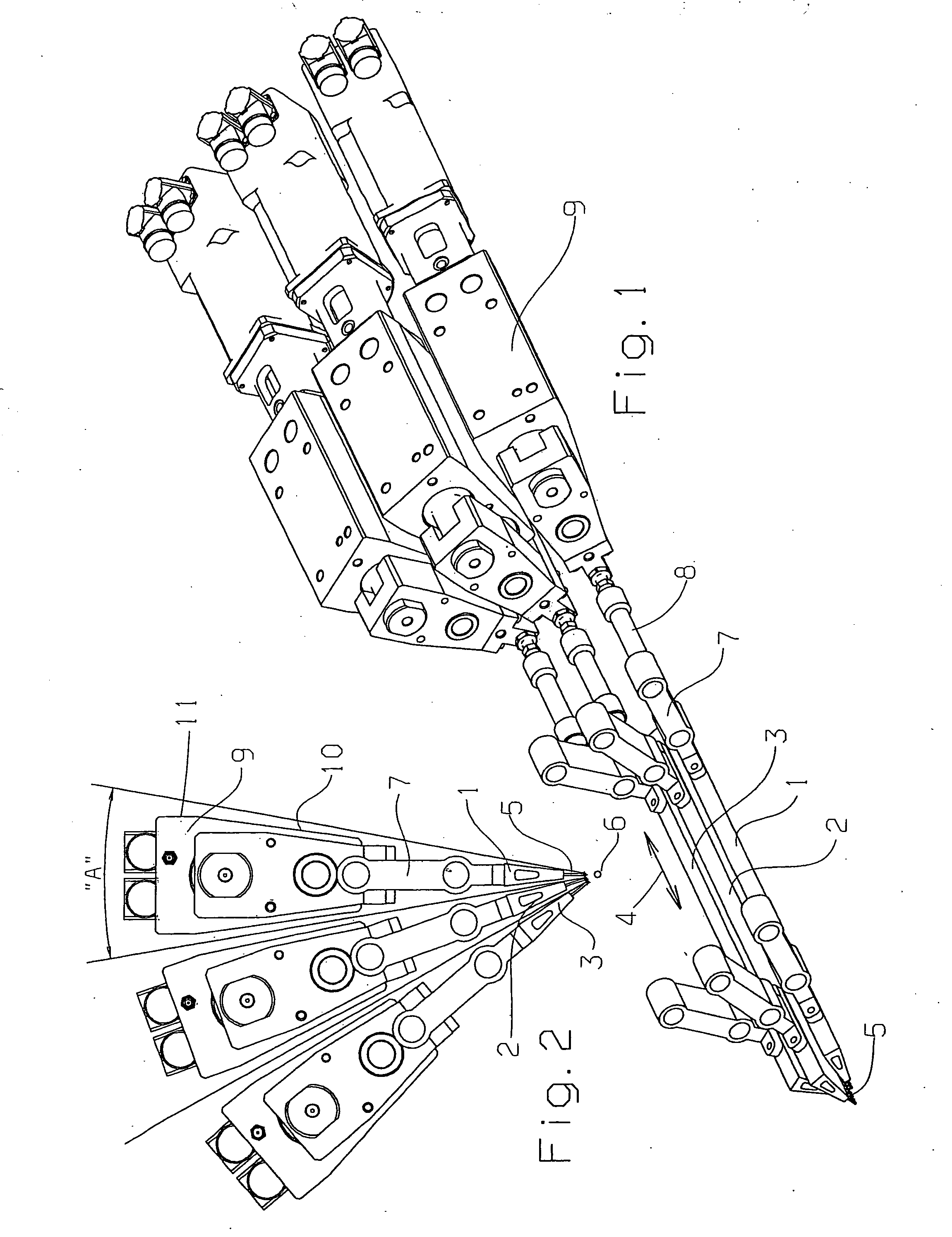
[0013] Drives that respectively fit into the angle segments are thus used for the guide bars. It is thus possible to arrange all the drives in the axial direction, i.e., movement direction of the guide bars, at the same position. The drive conditions for the guide bars are the same. This is achieved in structural terms in that the drives are no longer embodied with a constant width (perpendicular to the movement direction of the drive rails) across their height, but with a width that decreases in the direction of the working line. The "working line" is hereby an imaginary line at which the guides would intersect if they were extended. It is not absolutely necessary hereby for the extensions of all the guides to intersect at the working line. Minor deviations are permissible. The fact that the drives are constructed narrower in an area closer to the working line than in an area that is further away from the working line, makes it possible to stagger the drives relatively compactly in the width direction and to accommodate them in the individual angle segments so that they do not obstruct one another. In this manner all the guide bars or guide rails can be driven by the same drives. A nesting or the use of different extension levers is not necessary.
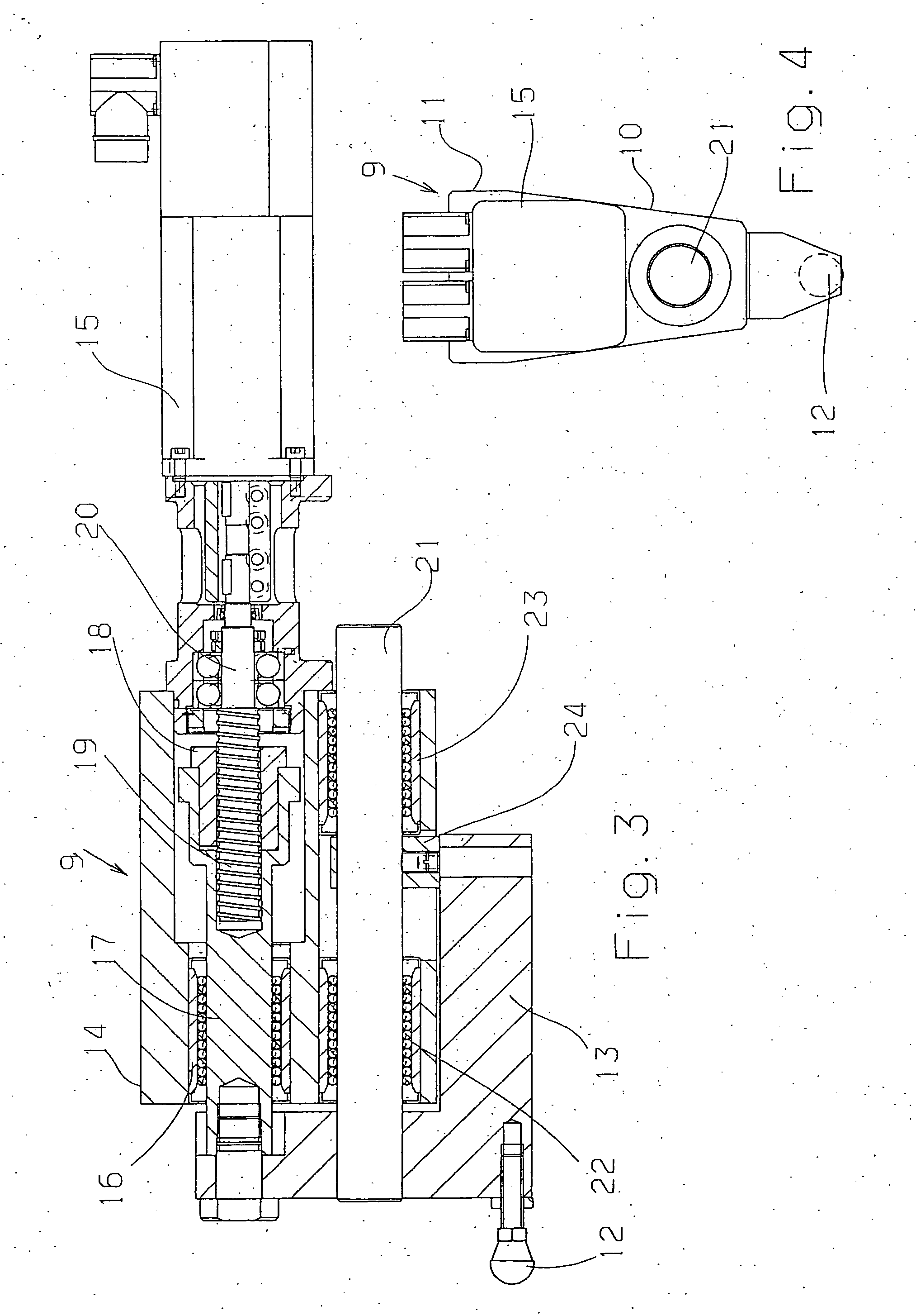
[0017] The first element preferably features a second attachment point on at least one guiding device. This provides an additional support for the first element so that tipping or tilting is avoided, even when greater forces are transmitted to the guide bars.
[0020] Qne of the guiding devices preferably features a ball screw. A rotary motion of the motor can be transmitted to the first element in a simple and relatively low-loss manner via a ball screw. Space is saved if this ball screw is arranged in a guiding device, so that the drive does not need to be excessively wide at this point.
[0023] The drive preferably features a section that tapers towards the working line. This section can be formed, e.g., by a housing section with sloping walls. Such an embodiment facilitates assembly. The side walls of the tapering sections can be aligned parallel to one another and the drives can thus be assembled in an easy manner.

Problems solved by technology

The guides thus emanate outwards from the imaginary working line in the form of radial beams, whereby the space that is available for the guides is limited due to the other elements of the knitting machine, such as needles, pile sinkers, knock-over sinkers, etc.
These have the disadvantage that they have to be replaced during pattern changes.
This is associated with great expense.
Long repeats are not possible with pattern disks.
However, the speed of the knitting machine has to be reduced when working with pattern chains.
However, such motors need a relatively large space.
However, disadvantages in terms of stability and energy consumption thus occur, because in part very large masses have to be moved.
In knitting machines that have several pattern guide bars in addition to several ground guide bars, the direct attachment of such drives is not possible for reasons of space.

Method used


Image

  • Knitting machine
  • Knitting machine
  • Knitting machine

Examples


Embodiment Construction

[0041] The particulars shown herein are by way of example and for purposes of illustrative discussion of the embodiments of the present invention only and are presented in the cause of providing what is believed to be the most useful and readily understood description of the principles and conceptual aspects of the present invention. In this regard, no attempt is made to show structural details of the present invention in more detail than is necessary for the fundamental understanding of the present invention, the description taken with the drawings making apparent to those skilled in the art how the several forms of the present invention may be embodied in practice.

[0042] A knitting machine (not shown in further detail) features several guide bars 1-3 that are moved backwards and forwards in the direction of a double arrow 4 in order to place threads, which have been guided through guides 5, around other knitting elements, e.g., needles, in a predetermined manner.

[0043] In order to...


PUM


Abstract

Knitting machine that includes a plurality of guide bars, guides, associated with the plurality of guide bars, which are aligned to a working line, and drives, connected to the plurality of guide bars via coupling points, which are arranged next to one another in adjacent angle segments emanating from the working line and having a smaller width in an area adjacent the working line than in an area distant from the working line. The instant abstract is neither intended to define the invention disclosed in this specification nor intended to limit the scope of the invention in any way.

Description

[0001] The present application claims priority under 35 U.S.C. .sctn.119 of German Patent Application No. 103 21 331.7, filed on May 13, 2003, the disclosure of which is expressly incorporated by reference herein in its entirety.[0002] 1. Field of the Invention[0003] The invention relates to a knitting machine with several guide bars connected to drives via coupling points, the guides of which guide bars are aligned to a working line.[0004] 2. Discussion of Background Information[0005] A knitting machine with several guide bars, which are also called "guide rails," is constructed so that the guide bars are arranged in a fan-shaped manner in cross section. The guides thus emanate outwards from the imaginary working line in the form of radial beams, whereby the space that is available for the guides is limited due to the other elements of the knitting machine, such as needles, pile sinkers, knock-over sinkers, etc. In principle, an angle segment is assigned to each guide bar. The angl...

Claims


Application Information

Patent Timeline
Patent Type & Authority Applications(United States)
IPC IPC(8): D04B15/38D04B27/30D04B15/54D04B27/10D04B27/26
CPCD04B27/26D04B15/38D04B15/54D04B27/10
Inventor MISTA, KRESIMIR
Owner KARL MAYER TEXTILMASCHFAB GMBH
Why Eureka
Try Eureka