Organic EL panel drive circuit and organic EL display device using the same drive circuit

Active Publication Date: 2005-01-06
ROHM CO LTD
View PDF3 Cites 25 Cited by
  • Summary
  • Abstract
  • Description
  • Claims
  • Application Information

AI Technical Summary

Benefits of technology

[0013] A first object of the present invention is to provide an organic EL panel drive circuit capable of improving display luminance by shortening a res

Problems solved by technology

One of the problems of a conventional organic EL display device is that the predetermined reset period is necessary and luminous intensity is degraded since light emitting period is shortened when scan frequency is increased.
However, a time period in which the potential of the organic EL elements must be increased from ground potential to the peak current becomes long.
Therefore, the substantial light emission period of the organic EL element is shortened, resulting in degradation of luminous intensities thereof.
Another problem of the conventional organic EL display device is that, when the voltage drive is used to drive terminal pins thereof as in a liquid crystal display device, a display control becomes difficult and luminance variation becomes conspicuous due to difference in lu

Method used


Image

  • Organic EL panel drive circuit and organic EL display device using the same drive circuit
  • Organic EL panel drive circuit and organic EL display device using the same drive circuit
  • Organic EL panel drive circuit and organic EL display device using the same drive circuit

Examples


Embodiment Construction

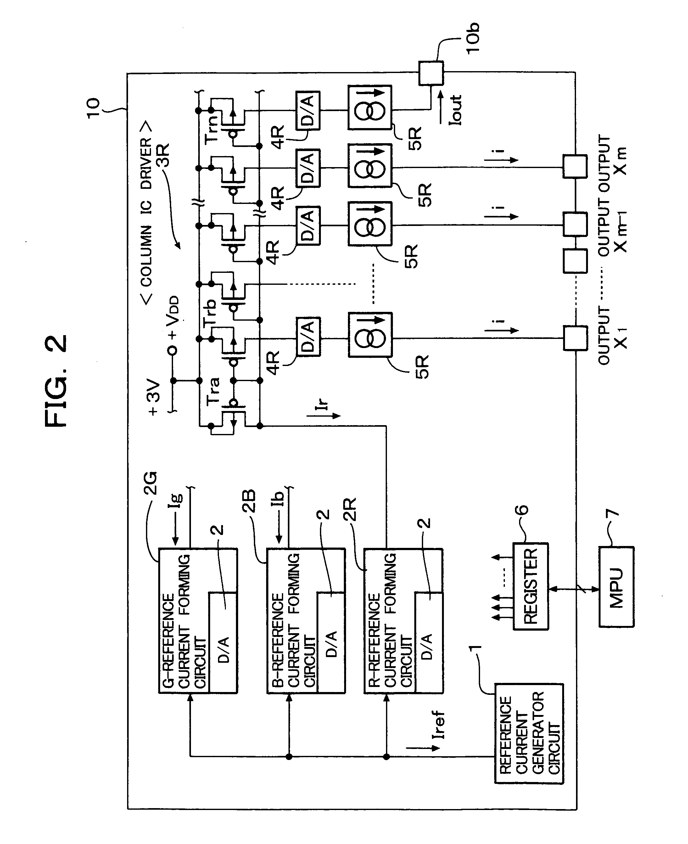
[0035] A column driver 10 shown in FIG. 2 is formed as an column IC chip functioning as an organic EL drive circuit of an organic EL panel. The column driver 10 includes a reference current generator circuit 1, a reference current forming circuit (R-reference current forming circuit) 2R provided for R (red) display color, a reference current forming circuit (G-reference current forming circuit) 2G provided for G (green) display color and a reference current forming circuit (B-reference current forming circuit) 2B provided for B (blue) display color.

[0036] Each of the reference current forming circuits 2R, 2G and 2B includes a current mirror circuit provided as an input, stage of the reference current forming circuit. The current mirror circuits of the reference current forming circuits 2R, 2G and 2B receive a reference current Iref generated by the reference current generator circuit 1 and form reference currents Ir, Ig and Ib corresponding to respective R, G and B display colors. ...


PUM


Abstract

A resetting period of organic EL elements is divided to a discharge period for discharging residual charges of the organic EL elements and a precharge period for pre-charging the organic EL elements to predetermined potentials. First switch circuits provided for each of R (red), G (green) and B (blue) display colors are turned ON in the discharge period to discharge residual charges of the organic EL elements and second switch circuits provided for each of R, G and B display colors are turned ON in the precharge period to precharge the EL elements to a precharge potential lower than a light emission voltage of the organic EL elements. Values of finally set precharge voltages for R, G and B display colors are made different from each other.

Description

BACKGROUND OF THE INVENTION [0001] 1. Field of the Invention [0002] The present invention relates to an EL (electro luminescent) element drive circuit and an organic EL display device using the same drive circuit and, in particular, the present invention relates to an organic EL display device suitable for high luminance color display, with which display luminance of organic EL elements can be improved and white balance on a display screen of an electronic device such as a portable telephone set or a PHS, etc., can be easily regulated by regulating luminous intensities of R (red), G (green) and B (blue) display colors even when dynamic range of regulation of reference current value of each of R, G and B colors is small. [0003] 2. Description of the Prior Art [0004] An organic EL display panel of an organic EL display device, which is mounted on a portable telephone set, a PHS, a DVD player or a PDA (personal digital assistance) and includes 396 (132×3) terminal pins for column lines...

Claims


Application Information

Patent Timeline
IPC IPC(8): G09G3/32G09G3/30H05B44/00
CPCG09G3/3283G09G2310/0251G09G2320/0666G09G2310/061G09G2320/0606G09G2310/027G09G3/30
Inventor KITAHARA, SHINJI
Owner ROHM CO LTD
Why Eureka
Try Eureka