Reflective liquid crystal display device

Inactive Publication Date: 2006-04-04
LG DISPLAY CO LTD
View PDF14 Cites 1 Cited by
  • Summary
  • Abstract
  • Description
  • Claims
  • Application Information

AI Technical Summary

Benefits of technology

[0026]An advantage of the present invention is to provide a reflective liquid crystal display (LCD) device having a cholesteric liquid crystal (CLC) color filter, which increases a luminance of displayed images.
[0027]Another advantage of the present invention is to provide a reflective liquid crystal display (LCD) device having a cholesteric liquid crystal (CLC) color filter, that implements a uniform luminance and uniform color within a main viewing angle range.
[0028]Additional features and advantages of the invention will be set forth in the description which follows, and in part will be apparent from the description, or may be learned by practice of the invention. The objectives and other advantages of the invention will be realized and attained by the structure particularly pointed out in the written description and claims hereof as well as the appended drawings.
[0029]To achieve these and other advantages and in accordance with the purpose of the present invention, as embodied and broadly described, a reflective liquid crystal display device includes a first substrate; an absorption layer on the first substrate; a cholesteric liquid cr

Problems solved by technology

However, the transmissive LCD device has high power consumption.
However, though an introduction of the diffusion f

Method used


Image

  • Reflective liquid crystal display device
  • Reflective liquid crystal display device
  • Reflective liquid crystal display device

Examples


first embodiment

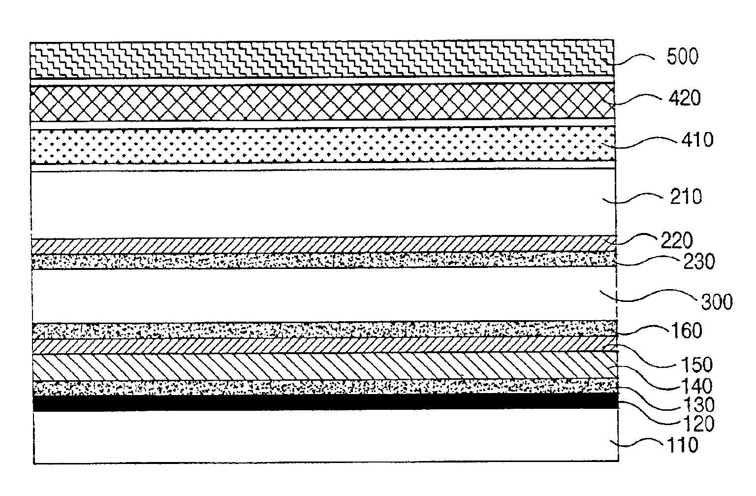
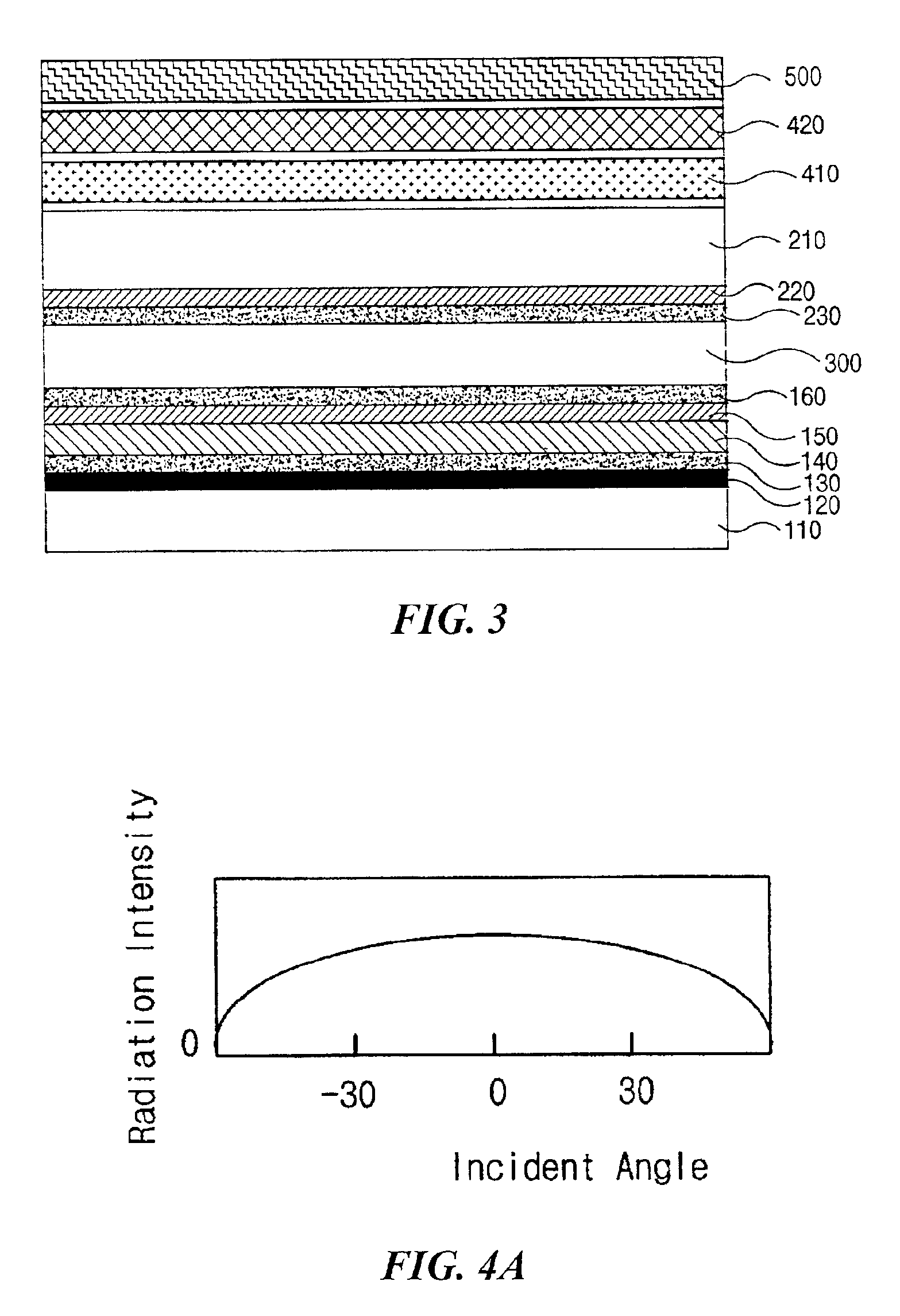
[0044]FIG. 3 is a cross-sectional view of a reflective liquid crystal display device that has a cholesteric liquid crystal (CLC) color filter according to the present invention.

[0045]In FIG. 3, a first substrate 110 and a second substrate 210 are spaced apart from each other. The second substrate 210 is formed of transparent insulating material, whereas the first substrate 110 may be formed of transparent material or opaque material. An absorption layer 120 is formed on the first substrate 110 to absorb light. A first alignment layer 130 made of polymer is formed on the absorption layer 120. A polyimide is usually selected for an alignment layer material because it exhibits good alignment characteristics with various liquid crystal materials. A cholesteric liquid crystal (CLC) color filter layer 140, which reflects a light of particular wavelength, is formed on the alignment layer 130. The first alignment layer 130 aligns liquid crystal molecules of the cholesteric liquid crystal (C...

second embodiment

[0053]However, since the reflective LCD device uses the ambient light as a light source to display images, the light may be incident on the LCD panel from one direction. In this case, a diffusion film may be required to diffuse the incident light as shown in FIG. 5. FIG. 5 is a cross-sectional view of a reflective liquid crystal display device that has a cholesteric liquid crystal (CLC) color filter according to the present invention.

[0054]The second embodiment shown in FIG. 5 has the same structure and configuration as the first embodiment shown in FIG. 3 except for a diffusion film 600. In FIG. 5, a first substrate 110 and a second substrate 210 are spaced apart from each other. The second substrate 210 is formed of transparent insulating material, whereas the first substrate 110 may be formed of transparent material or opaque material. An absorption layer 120 is formed on the first substrate 110 to absorb light. A first alignment layer 130 made of polymer is formed on the absorpt...


PUM


Abstract

A reflective LCD device having a CLC color filter includes a holographic film to increase a luminance and viewing angle. Due to the holographic film, light incident to the CLC film has not only a small incident angle but also a small reflection angle. Therefore, a wavelength variation decreases. Further, since the holographic film diffuses the reflected light, a chromaticity variation also decreases. Since the reflective LCD device of the present invention further includes the diffusion film on the holographic film, the incident light can have a wide range of incident angle and the reflected light can be further diffused.

Description

[0001]This application claims the benefit of Korean Patent Application No. 2001-25709 filed on May 11, 2001 in Korea, which is hereby incorporated by reference as if fully set forth herein.BACKGROUND OF THE INVENTION[0002]1. Field of the Invention[0003]The present invention relates to a liquid crystal display (LCD) device and more particularly, to a reflective LCD device having a cholesteric liquid crystal (CLC) color filter layer.[0004]2. Discussion of the Related Art[0005]Flat panel display devices, which have properties of being thin and low weight and having low power consumption, are in high demand in the display field as the information age rapidly evolves.[0006]The flat panel display device may be classified into two types depending on whether it emits or receives light. One type is a light-emitting type display device that emits light to display images and the other type is a light-receiving type display device that uses an external light source to display images. Plasma dis...

Claims


Application Information

Patent Timeline
IPC IPC(8): G02F1/1335
CPCG02F1/133504G02F1/133514G02F2203/02G02F1/1335
Inventor YOON, SUNGHOE
Owner LG DISPLAY CO LTD
Why Eureka
Try Eureka