Video display device and television receiving device

a technology of video display device and television, which is applied in the direction of color television details, color signal processing circuits, instruments, etc., can solve the problems of brightness and contrast feeling becoming unnatural, and achieve the effects of enhancing the luminance of the light emitting portion, increasing the luminance of the light source, and enhancing processing

Inactive Publication Date: 2015-01-08
SHARP KK
View PDF28 Cites 5 Cited by
  • Summary
  • Abstract
  • Description
  • Claims
  • Application Information

AI Technical Summary

Benefits of technology

[0023]According to the video display device of the present invention, the display luminance of the light emitting portion is enhanced (a light emitting portion enhancement processing) to be distinctly displayed by increasing the luminance of the light source by stretching the luminance based on the input video signal; detecting the light emitting portion of the video from the video signal; and reducing the luminance of the video signal of the non-light emitting portion except the light emitting portion. Thereby, the video expression is enabled whose feeling of brightness and contrast feeling are increased. It is detected whether any instruction is issued to display on the display portion the second input video signal together with the first input video signal, and the control of the light emitting portion enhancement processing is switched according to the result of the detection. Therefore, for example, when the multi-screen display is executed, the feeling of brightness and the contrast feeling can be prevented from becoming unnatural by discontinuing the light emitting portion enhancement processing, etc.

Problems solved by technology

However, when the light emission luminance is adjusted simply corresponding to the APL, for multi-screen display displaying both of a dark video and a bright video, the light emission luminance becomes the one that corresponds to an intermediate APL between the APL of the dark video and the APL of the bright video, and therefore, the feeling of brightness and the contrast feeling become unnatural.

Method used


Image

  • Video display device and television receiving device
  • Video display device and television receiving device
  • Video display device and television receiving device

Examples


first embodiment

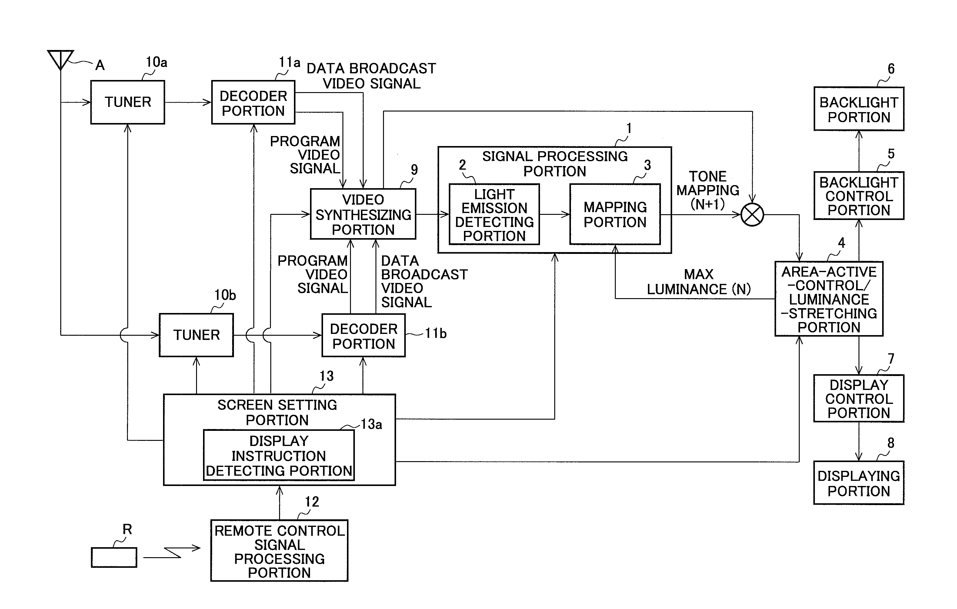
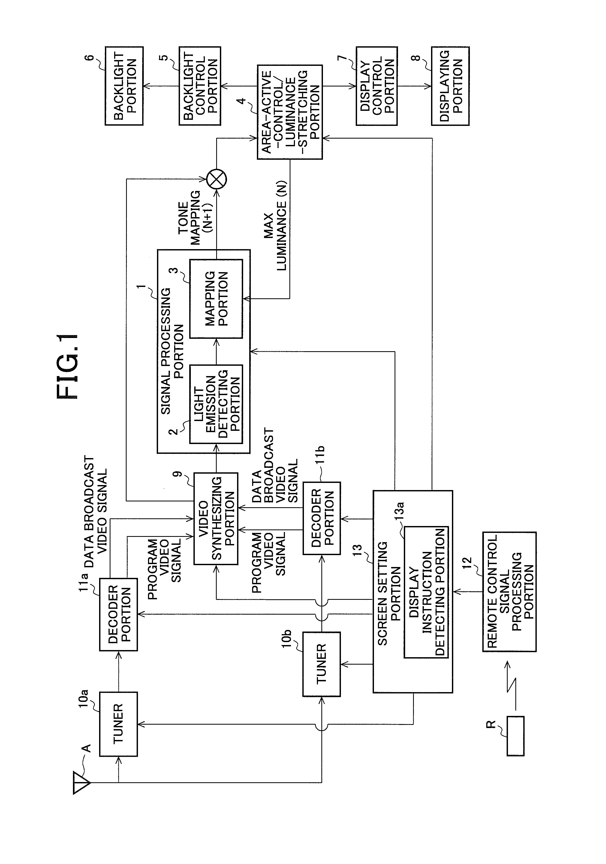
[0044]FIG. 1 is a diagram for explaining an embodiment of a video display device according to the present invention and depicts an exemplary configuration of the purview of the video display device. The video display device displays a video acquired by applying image processing to an input video signal, and for example, the video display device constitutes, for example, a television receiving device.

[0045]The video display device exemplified in FIG. 1 includes a signal processing portion 1, an area-active-control / luminance-stretching portion 4, a backlight control portion 5, a backlight portion 6, a display control portion 7, a displaying portion 8, a video synthesizing portion 9, tuners 10a and 10b, decoder portions 11a and 11b, a remote control signal processing portion 12, and an image setting portion 13.

[0046]The signal processing portion 1 includes a light emission detecting portion 2 and a mapping portion 3. The image setting portion 13 includes a display instruction detecting...

second embodiment

[0129]FIG. 10 is a diagram for explaining another embodiment (a second embodiment) of the video display device: according to the present invention and depicts another exemplary configuration of the purview of the video display device.

[0130]The video display device of the second embodiment has the same configuration as that of the video display device of the first embodiment but differs from the video display device of the first embodiment in that the area-active-control / luminance-stretching portion 4 does not determine the value of the Max luminance used when the tone mapping is executed; the light emission detecting portion 2 determines the luminance stretch amount based on the result of the detection of the light emitting portion; and the mapping portion 3 executes the tone mapping based on the determined luminance stretch amount. Therefore, not as in the first embodiment, the mapping portion 3 does not need to acquire the Max luminance value by the luminance stretching from the a...

third embodiment

[0148]FIG. 13 is a diagram for explaining another embodiment (a third embodiment) of the video display device according to the present invention and depicts another exemplary configuration of the purview of the video display device.

[0149]The video display device of the third embodiment has the same configuration as that of the video display device in the second embodiment; and executes the same operation as that in the second embodiment; but differs from the video display device of the second embodiment in that this video display device includes a luminance stretching portion 4a that does not executes the area active control, instead of the area-active-control / luminance-stretching portion 4. The luminance stretching portion 4a stretches the luminance of the backlight portion 6 using the luminance stretch amount output from the mapping portion 3 of the signal processing portion 1.

[0150]The luminance stretching portion 4a is input with the video signal to which the tone mapping is app...


PUM


Abstract

The present invention makes possible video expressions with increased feeling of brightness and increased contrast feeling and to be able to prevent the feeling of brightness and the contrast feeling from becoming unnatural during execution of the multi display. This video display device comprises: a control portion (a signal processing portion (1); an area-active-control/luminance-stretch-portion (4)) that controls a displaying portion (8) and a backlight portion (6); and a display instruction detection portion (13a) that detects display instructions of first and second input video signals. The control portion stretches and increases the luminance of the backlight portion (6), and also controls a light emitting portion enhancement processing according to a result of the detection. In the light emitting portion enhancement processing, the display luminance of a light emitting portion is enhanced by producing a histogram by integrating number of pixels for a predetermined feature amount relating to the brightness of the input video signal, detecting an upper region of a predetermined range of the histogram as the light emitting portion, and reducing luminance of a video signal of non-light emitting portion except the light emitting portion of the input video signal.

Description

TECHNICAL FIELD[0001]The present invention relate to a video display device and a television receiving device, and more particularly, to a video display device and a television receiving device that each include an enhancement function to improve the image quality of the displayed video.BACKGROUND OF THE INVENTION[0002]For a liquid crystal display apparatus including a liquid crystal panel that modulates the light source light according to a video signal, and a backlight light source to illuminate the liquid crystal panel, a technique is known according to which the quality level of the displayed video is improved by controlling the light emission luminance of the backlight light source corresponding to an input video signal.[0003]For example, Patent Document 1 discloses a liquid crystal display apparatus that calculates the average picture level (hereinafter, referred to as “AFL”) in one frame as a feature amount of an input video signal and adjusts the light emission luminance of ...

Claims


Application Information

Patent Timeline
Patent Type & Authority Applications(United States)
IPC IPC(8): H04N9/64H04N9/30
CPCH04N9/30H04N9/646G09G3/3426G09G2320/0271G09G2360/16G09G3/3406G09G2320/062G09G2320/064G09G2320/0646G09G2320/0653G09G2320/066G09G3/2092
Inventor FUJINE, TOSHIYUKISHIRAYA, YOJI
Owner SHARP KK
Why Eureka
Try Eureka