Eureka AIR delivers breakthrough ideas for toughest innovation challenges, trusted by R&D personnel around the world.

Winding device of winding wheel and wire

Inactive Publication Date: 2005-01-13
WEI JOSE
View PDF2 Cites 7 Cited by
  • Summary
  • Abstract
  • Description
  • Claims
  • Application Information

AI Technical Summary

Benefits of technology

[0008] Therefore, a primary object of the invention is to provide a winding device of a winding wheel and a wire (signal wire), wherein when the wire is repeatedly withdrawn and pulled out from an elastically rotatable winding wheel, the wire is prevented from damages and displacements resulted from stiff friction between the wire and wedge apertures at wheel breadths.

Problems solved by technology

However, wires that are pulled using such method in the long run are prone to the following drawbacks:
In the long run, the left and right wires W1 and W2 may be resulted with breakage in conducting copper wires thereof, hence leading to poor contact.

Method used


Image

  • Winding device of winding wheel and wire
  • Winding device of winding wheel and wire
  • Winding device of winding wheel and wire

Examples


example

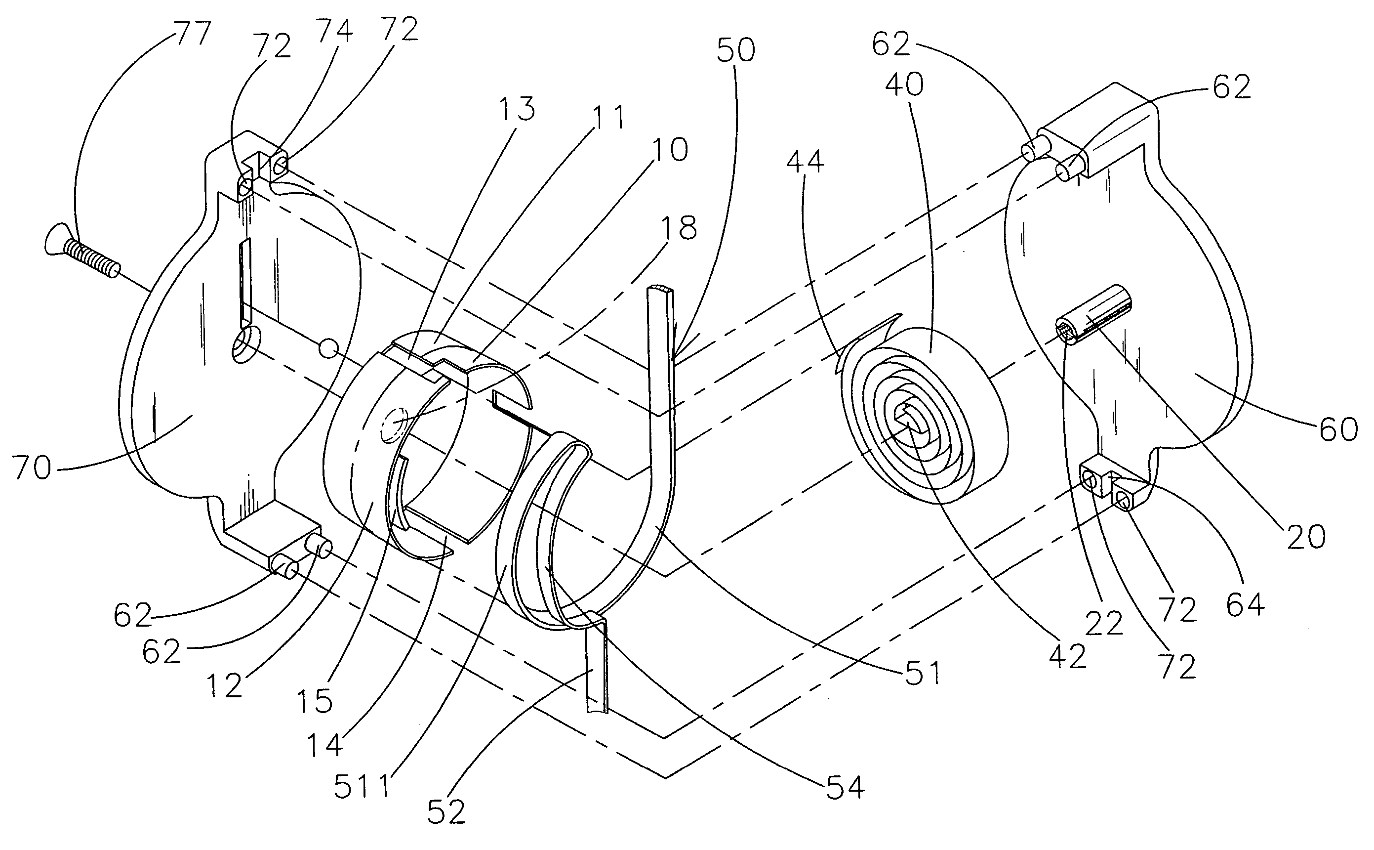
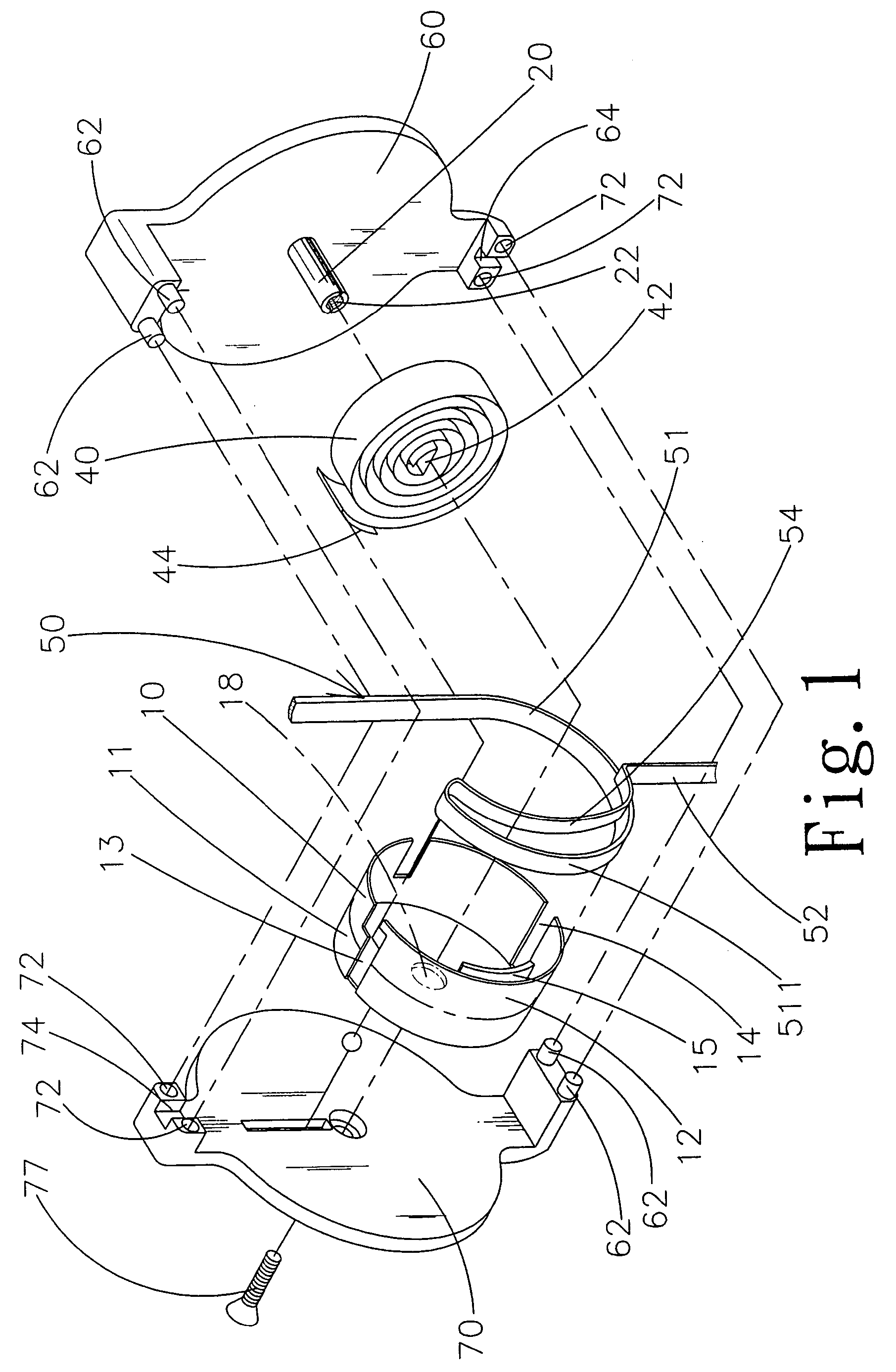
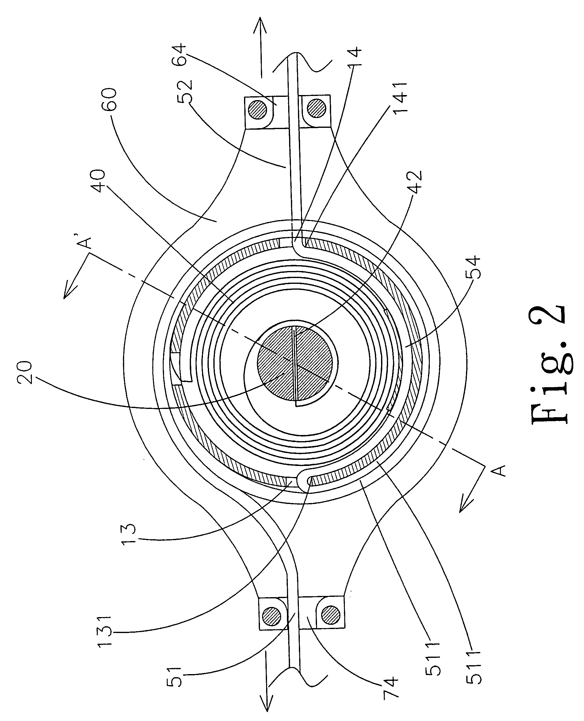
[0021] 1. Referring to FIG. 1, an inner side of the turning wheel 10 having a constant outer diameter is accommodated by a spring 40. The fixed shaft 20 is fastened at an inner surface of a right casing 60, and a left casing 70 is fastened to the fixed shaft 20 by screwing a screw bolt 77 into a screw opening 22 at an end portion of the fixed shaft 20. The left and right casings 70 and 60 are joined by inserting an insertion column 62 into an insertion opening 72, so as to construct a wire winding mechanism and form wire storage chambers at upper spaces of the left and right wheel breadths 11 and 12. The spring 40 has an inner end 42 fixed to the fixed shaft 20, and an outer end 44 fixed to a wall surface of the turning wheel 10. Using the aforesaid structure, the turning wheel 10 becomes capable of elastically rotatable in both forward and reverse directions using the fixed shaft 20 as an axis of rotation. Referring to FIG. 2, the left wire 51 is guided out to an exterior via an up...


PUM


Abstract

A winding device of a winding wheel and a wire includes an elastically rotatable turning wheel having a flexibly connected fixed shaft, wheel breadths defining a left wheel breadth and a right wheel breadth, and a continuous wire defining left and right wires. A number of rounds of the left wire winded at the left wheel breadth is at least one more than that of the right wire winded at the right wheel breadth, such that when the left and right wires are released from the left and right wheel breadths to reach outer dead centers thereof, at least one round of basic coil of the left wire still tightly binds around the left wheel breadth and remains unreleased. The wire (signal wire) is prevented from damages and displacements resulted from shear force between the wire and wedge apertures at the wheel breadths when repeatedly withdrawn and pulled thereof.

Description

BACKGROUND OF THE INVENTION [0001] (a) Field of the Invention [0002] The invention relates to a winding device of a winding wheel and a wire (signal wire). More particularly, to a winding device, wherein when two ends of a signal wire are pulled out from breadths of a turning wheel thereof by force accepted, shear force at connecting portions of the signal wire and the wheel breadths is not resulted, thereby preventing damages of wire surfaces or conductive wires by eliminating stiff friction between the signal wire and the connecting portions. [0003] (b) Description of the Prior Art [0004] Referring to FIG. 6 showing a typical winding device, “USB Transmission Cable having Cable Winding Mechanism” disclosed by Taiwan Patent Publication No. 529819, the invention comprises an elastically rotatable turning wheel A flexibly connected to a fixed shaft B, and a spring C having an inner end thereof fastened to the fixed shaft B and an outer end thereof fastened to a wall surface of the el...

Claims


Application Information

Patent Timeline
IPC IPC(8): B65H75/40H02G11/02
CPCB65H75/4434H02G11/02B65H2701/37B65H2701/34B65H75/34
Inventor WEI, JOSE
Owner WEI JOSE
Why Eureka
Eureka Blog
Learn More