
Packet transceiver apparatus

a transceiver and packet technology, applied in the field of packet transceiver apparatus, can solve the problems of data reception error, large time pass from the time of initial packet transmission, and variability of interference characteristics in relation to other receiving stations or adjacent cells

Inactive Publication Date: 2005-01-13
FUJITSU LTD
View PDF11 Cites 24 Cited by
  • Summary
  • Abstract
  • Description
  • Claims
  • Application Information

AI Technical Summary

Benefits of technology

The present invention provides a solution for transmitting data packets in a communication system that can adapt to changing conditions of the propagation path. By comparing modulation parameters and packet data, the invention allows for accurate transmission even if the initial conditions of the propagation path differ from those at the time of retransmission. This results in efficient use of radio resources, prevention of repeated packet reception failures, and avoidance of excessive allocation of radio resources. Additionally, the invention provides a method for extracting data from a buffer and combining it with the retransmitted data, allowing for efficient use of the buffer.

Problems solved by technology

However, since the transmission power varies in this scheme, the interference characteristic in relation to other receiving stations or adjacent cells also may vary.
If multiple retransmissions are performed, a considerable length of time passes from the time of the initial packet transmission.
If a packet that has undergone signal modulation based upon a modulation parameter identical with that which prevailed at the time of initial transmission is transmitted in such case, data reception error will occur or it will no longer be possible to transmit data efficiently.
A data reception error will result.
Conversely, if the conditions of the propagation path initially are worse than those at the time of a retransmission, then the quantity of transmit data will decline despite the fact that conditions allow a large quantity of data to be transmitted.
The result is a decline in transmission efficiency.

Method used


Image

  • Packet transceiver apparatus
  • Packet transceiver apparatus
  • Packet transceiver apparatus

Examples


Embodiment Construction

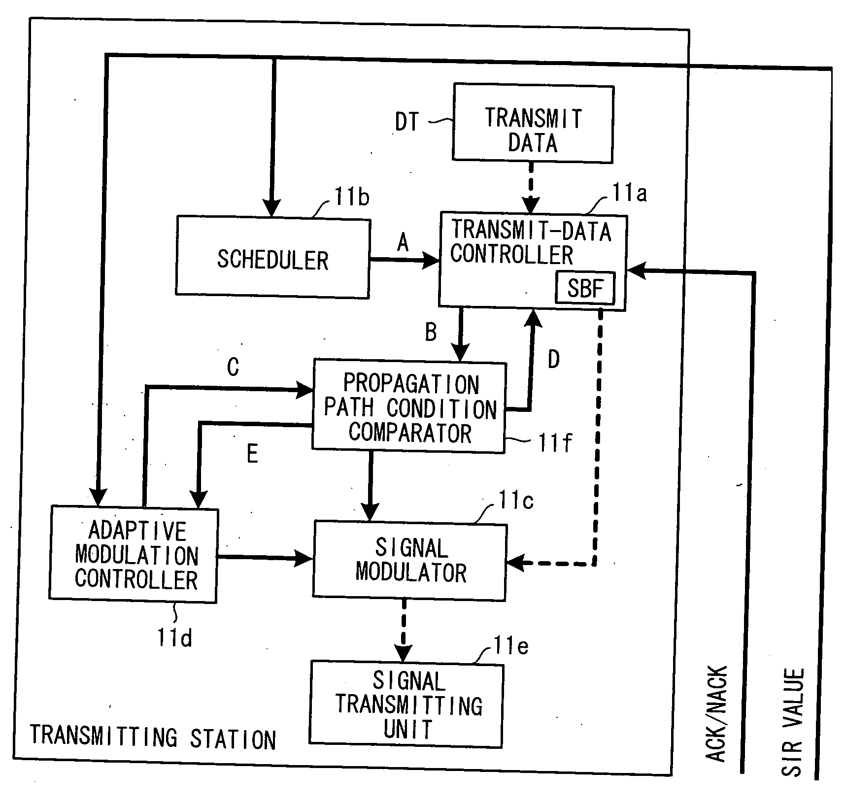
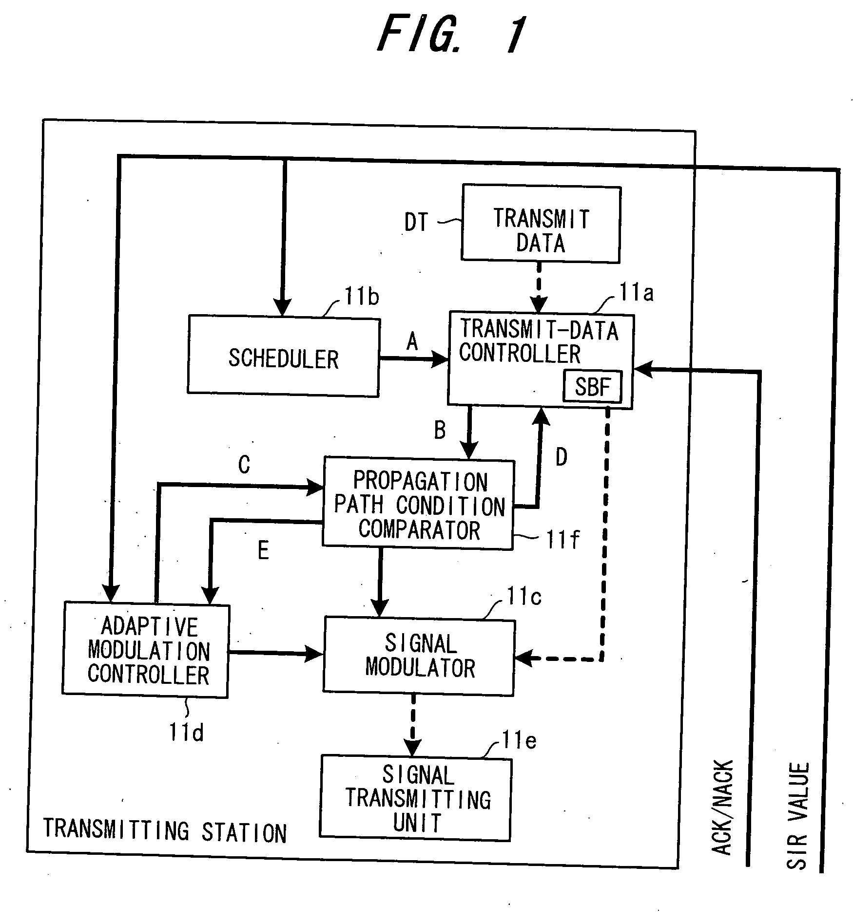
[0077] (A) Overall Operation of the Present Invention

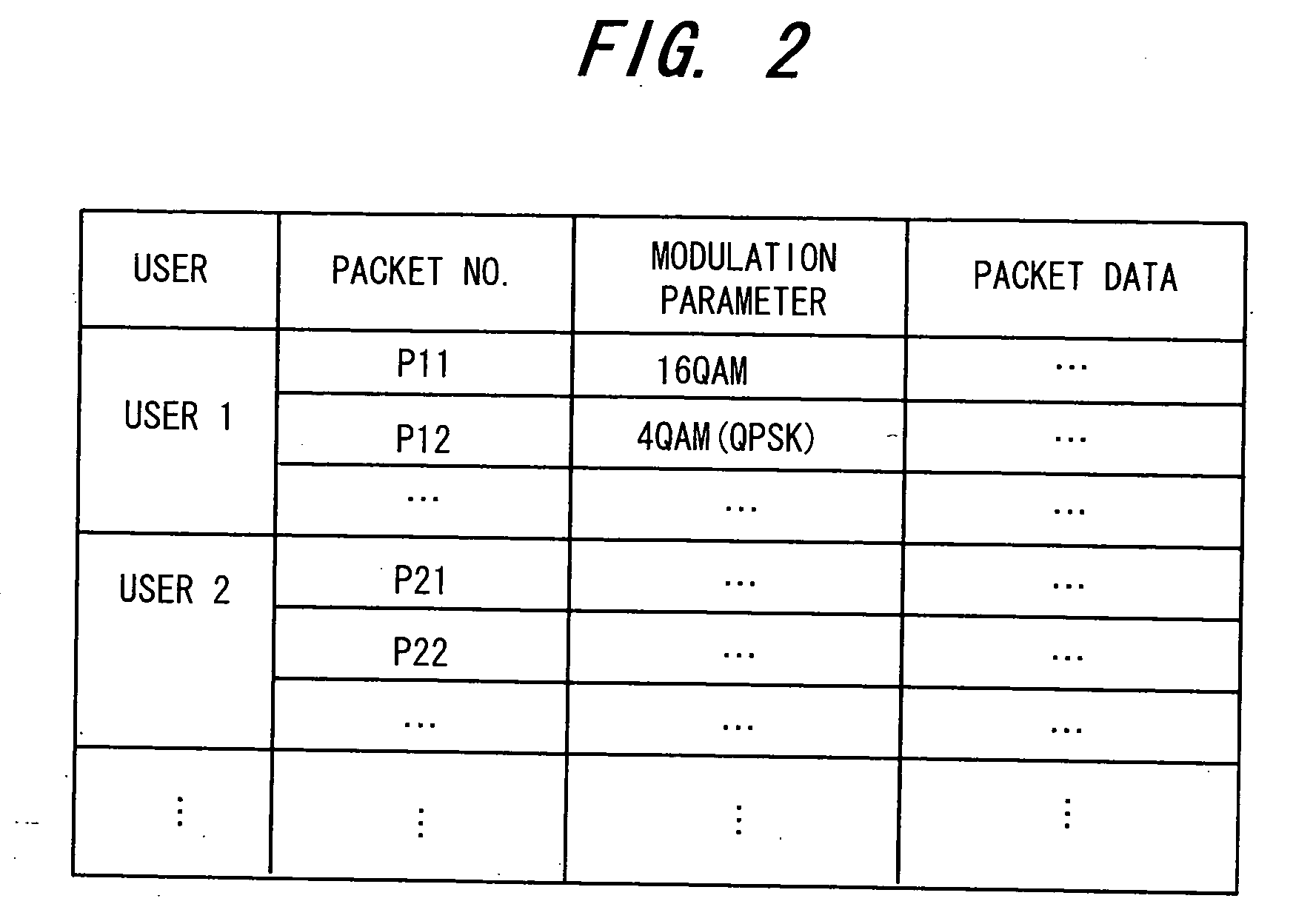
[0078]FIG. 1 is a block diagram of retransmission control implemented by a transmitting station in conformity with conditions of a propagation path according to the present invention. The dashed lines in FIG. 1 indicate the flow of data signals and the solid lines indicate the flow of control signals. Transmit data DT (data that is actually transmitted via a network) generated on a per-mobile-station basis is accumulated in a signal buffer SBF within a transmit-data controller 11a at one time. Implementations of the signal buffer include one in which retransmitted data and new data are kept separate from each other, one in which these items of data are kept together, and one in which these items of data are kept separate or kept together depending upon the type of traffic. FIG. 2 is a diagram useful in describing transmit data in the signal buffer SBF. The buffer stores, user by user, the modulation parameter (e.g., the type of d...


PUM


Abstract

Disclosed is a packet receiving apparatus in a communication system for transmitting a packet signal upon changing over a parameter of a transmit signal in accordance with conditions of a propagation path, and, when the packet signal cannot be received correctly on a receiving side, retransmitting the packet signal, combining the packet data received previously and the retransmitted packet data and executing decode processing based upon the combined packet data. The receiving apparatus is such that if the propagation path conditions at the time of retransmission are inferior, part of the packet data extracted from a buffer is cut out and combined with a retransmission packet and decode processing is executed based upon the result of combining. If the propagation path conditions at the time of retransmission are superior, data of a plurality of packets to undergo retransmission combining is extracted from the buffer, the extracted data is combined with part of a retransmission packet and decode processing is executed based upon the result of combining.

Description

BACKGROUND OF THE INVENTION [0001] This invention relates to a packet transceiver apparatus in a communication system and, more particularly, to a packet transceiver apparatus for transmitting packets efficiently in accordance with the conditions of the propagation path in a mobile communication system that transmits packets. [0002] There is growing demand for Internet services that employ mobile communication systems. Packet transmission schemes are suitable as means for the efficient transmission of signals having various qualities and transmission rates. In particular, efficient transmission of large quantities of data on the downlink from the base station to each of the mobile stations is desired. Packet transmission is characterized in that a signal is transmitted only when user data is generated and in that a channel can be shared by multiple users. Radio resources can therefore be used efficiently. Adaptive modulation, scheduling and retransmission also are available as means...

Claims


Application Information

Patent Timeline
Patent Type & Authority Applications(United States)
IPC IPC(8): H04L1/16H04B7/26H04J13/00H04L1/00H04L1/18H04L12/70H04L29/08H04W28/04
CPCH04L1/0003H04L1/005H04L1/0069H04L27/3488H04L1/1845H04L1/1887H04L1/1819
Inventor TANAKA, YOSHINORISEKI, HIROYUKITAKEO, KOHJI
Owner FUJITSU LTD
Learn More