NC lathe

a technology of nc lathes and turning plates, which is applied in the direction of turning machine accessories, other manufacturing equipment/tools, manufacturing tools, etc., can solve the problems of reduced machining accuracy, low workability of operators, and inability to raise the feed speed of the lathes

Active Publication Date: 2006-05-16
DMG MORI CO LTD
View PDF18 Cites 33 Cited by
  • Summary
  • Abstract
  • Description
  • Claims
  • Application Information

AI Technical Summary

Benefits of technology

[0036]Hence, with the NC lathe in accordance with the present invention, when the movable frame is moved, the loads applied to drive motors constituting the first feed device can be reduced, and the feed speed of the movable frame can be raised. Furthermore, at the start and stop of the movement of the movable frame, the influence of inertia is reduced, whereby the movable frame is prevented from being bent.
[0038]With this configuration, the first and second driven members fixed to the horizontal side positions of the movable frame are moved by the first and second drive members, respectively, whereby the movable frame can be moved in the first-axis direction. Since both ends of the movable frame can be driven, wobbling or attitude unsteadiness during the movement of the movable frame can be prevented, and highly accurate machining can be carried out.
[0040]With this configuration, chips generated during workpiece machining do not fall down or accumulate onto the bed but directly drop downward, unlike the configuration of the conventional lathe. Hence, trouble wherein chips enter the guide faces provided on the bed and the accuracy of the guidance is lowered can be prevented.
[0041]Still further, the front face of the bed is formed in a vertical face, the second tool rest is moved in the first-axis direction (the horizontal direction) and the second-axis direction (the vertical direction) along the front vertical face of the bed, the first tool rest is provided above the axis line of the main spindle, and the second tool rest is provided below the axis line. Hence, the main spindle, the first tool rest and the second tool rest are positioned further frontward (closer to the operator) from the front face of the bed, whereby the operator can easily carry out various operations for the main spindle, the first and second tool rests. Moreover, since the bed can be made smaller than the conventional bed that is formed so as to become broad toward the bottom, the entire size of the machine can be made compact.
[0043]With this configuration, a position closer to the central portion of the first saddle can be driven by the second feed device to move the first saddle. Hence, the first saddle can be moved smoothly without causing wobbling or attitude unsteadiness, whereby highly accurate machining can be attained.
[0048]To solve this problem, a sliding guide mechanism requiring maintenance is provided on the front side of the quill, and a rolling guide mechanism requiring no maintenance is provided on the rear side of the quill as described above. With this configuration, the guide mechanisms can be maintained without removing the quill from the accommodation hole in the first saddle, whereby efficient maintenance can be carried out while guidance stability is ensured.

Problems solved by technology

Because of the heavy weight of the column 116 serving as a movable body, the above-mentioned conventional NC lathe 100 has problems; that is, the load applied to a drive motor constituting a feed device (not shown) is large, the feed speed thereof cannot be raised, and the column 116 is apt to bend under the influence of inertia at the start and stop of the movement, thereby causing reduction in machining accuracy.
Hence, the size of the lower end of the bed 101 becomes large naturally, and the distances from the front end of the bed 101 to the main spindles 103 and 106 and the second tool rest 115 are large, thereby causing problems; that is, operator workability is low (it is difficult for the operator to come close to the workpiece machining area), and a wide installation area is required.
Still further, when the tool rest body 118 of the second tool rest 115 is rotated in the B-axis direction, the tool T held in the tool rest body 118 may be hidden behind the storage box 120 depending on the rotation angle position thereof, thereby causing inconvenience; that is, it is difficult for the operator to check the position and state of the tool T.

Method used


Image

  • NC lathe
  • NC lathe
  • NC lathe

Examples


Embodiment Construction

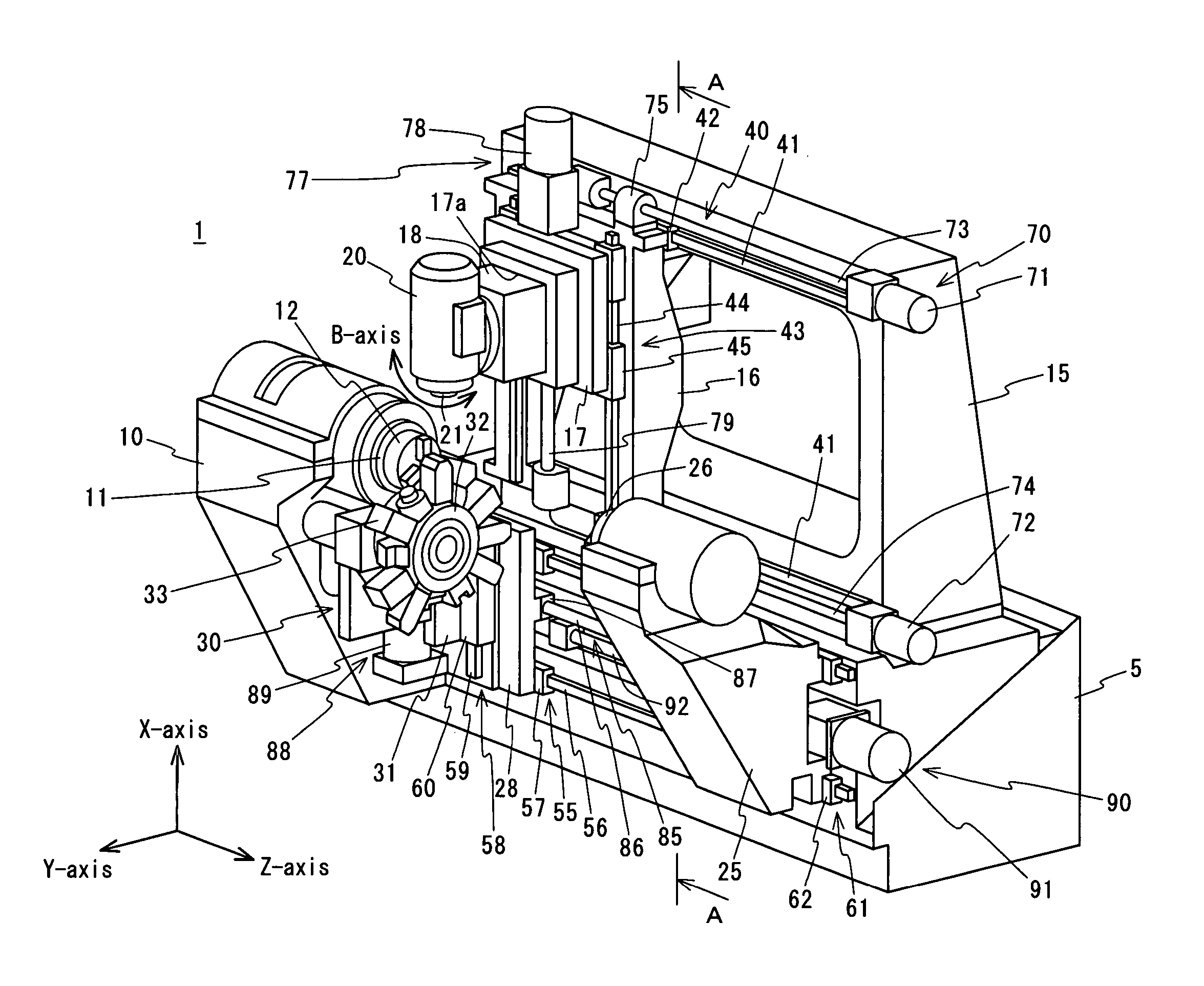
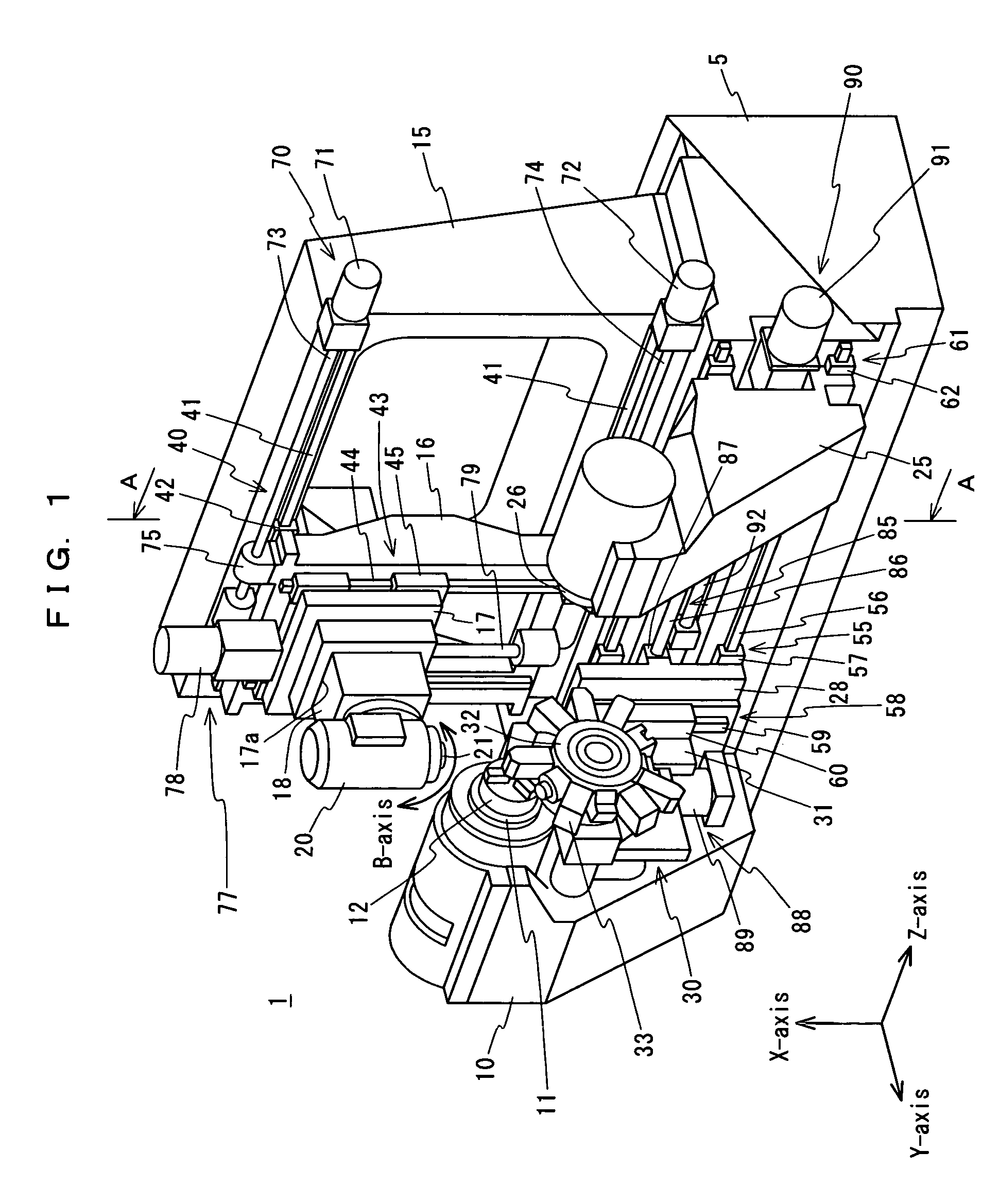
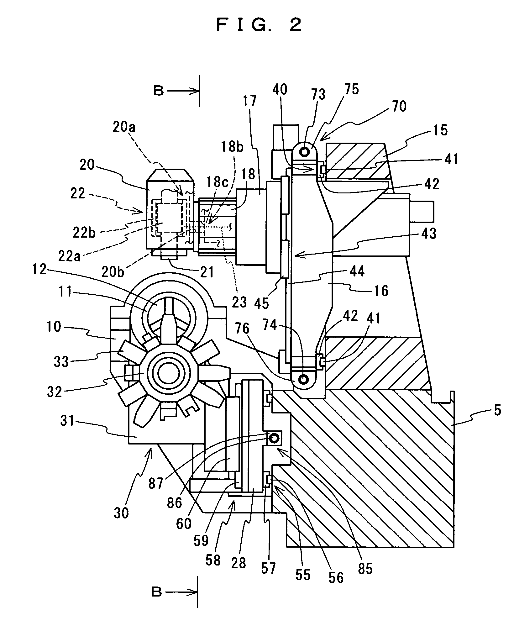
[0059]A preferred embodiment of the present invention will be described below with reference to the accompanying drawings. FIG. 1 is a perspective view showing a schematic configuration of an NC lathe in accordance with an embodiment of the present invention. FIG. 2 is a cross-sectional view taken in the arrow-indicated A—A direction of FIG. 1. FIG. 3 is a front view taken in the arrow-indicated B—B direction of FIG. 2. FIG. 4 is a cross-sectional view taken in the arrow-indicated C—C direction of FIG. 3. FIG. 5 is a cross-sectional view taken in the arrow-indicated D—D direction of FIG. 3. FIG. 6 is a cross-sectional view taken in the arrow-indicated E—E direction of FIG. 4.

[0060]As shown in FIGS. 1 to 6, the NC lathe 1 in accordance with this embodiment comprises a bed 5 formed in a rectangular shape so that the upper face is horizontal and so that the front face is vertical, a first headstock 10 provided on the front face of the bed 5, a first main spindle 11 supported by the fir...


PUM

PropertyMeasurementUnit
shapeaaaaaaaaaa
movementaaaaaaaaaa
weightsaaaaaaaaaa

Abstract

An NC lathe 1 comprises a bed 5, a headstock 10 provided on the bed 5, a main spindle 11 supported on the headstock 10 so as to be rotatable around the axis thereof, a rotation drive device for rotating the main spindle 11, a stationary frame 15 formed in a rectangular frame shape and fixed to the upper face of the bed 5, a movable frame 16 formed in a rectangular frame shape and provided so as to be movable in the Z-axis direction with respect to the stationary frame 15, a saddle 17 provided so as to be movable in the X-axis direction with respect to the movable frame 16, a quill 18 accommodated inside the accommodation hole 17a in the saddle 17 and provided so as to be movable in the Y-axis direction, and a tool rest 20 supported on the quill 18.

Description

BACKGROUND OF THE INVENTION[0001]1. Field of the Invention[0002]The present invention relates to an NC lathe comprising a headstock for rotatably supporting a main spindle for holding a workpiece, and a tool rest for holding a tool, the tool rest being movable in a predetermined feed direction.[0003]2. Description of the Prior Art[0004]Conventionally, a machine tool having a structure shown in FIGS. 7 and 8 is known as an NC lathe. This NC lathe 100 comprises a bed 101 formed in the shape of a triangular prism becoming broad toward the bottom, and a first headstock 102, a second headstock 105, a first tool rest 110, a second tool rest 115 and the like provided on the bed 101 as shown in FIGS. 7 and 8 (refer to Japanese Unexamined Patent Publication No. 2002-59301).[0005]The first and second headstocks 102 and 105 rotatably support main spindles 103 and 106 around the axes thereof, respectively, and are provided with rotation drive devices (not shown) for rotating the main spindles 1...

Claims


Application Information

Patent Timeline
Patent Type & Authority Patents(United States)
IPC IPC(8): B23P23/02B23B3/18B23B3/30B23Q1/00B23Q1/01B23Q1/62
CPCB23B3/168B23Q1/012B23Q1/626B23Q39/027Y10T409/307728Y10T82/2524Y10T82/25Y10T82/2566Y10T29/5114Y10T409/305656Y10T82/2541Y10T82/2508
Inventor TOKUMA, TSUTOMUNAKAMINAMI, MASAMITSU
Owner DMG MORI CO LTD
Why Eureka
Try Eureka