
Process for producing wear-resistant surface layers

a technology of surface layer and laser, which is applied in the field of process for the effective production of highly wear-resistant layers, can solve the problems of affecting the effect of the process cycle, the specific cost of providing energy is much higher with the laser than with other conventional energy sources, and the layer produced by the laser build-up welding process is too expensive, so as to achieve the effect of reducing the requirements for the following process cycle, increasing the feed rate and reducing the requirements of power and power density

Inactive Publication Date: 2005-01-18
FRAUNHOFER GESELLSCHAFT ZUR FOERDERUNG DER ANGEWANDTEN FORSCHUNG EV
View PDF7 Cites 24 Cited by
  • Summary
  • Abstract
  • Description
  • Claims
  • Application Information

AI Technical Summary

Benefits of technology

The invention provides a new kind of preheating process for finishing surface layers and thereby, in particular, for laser surface layer finishing, with which substantially higher feed rates can be achieved while simultaneously avoiding cracks in the layer or the substrate material even when applied to substrate materials susceptible to cracking such as, e.g., martensitic hardenable steels or steels susceptible to heat treatment cracking and very wear-resistant, very hard coating materials with limited ductibility.
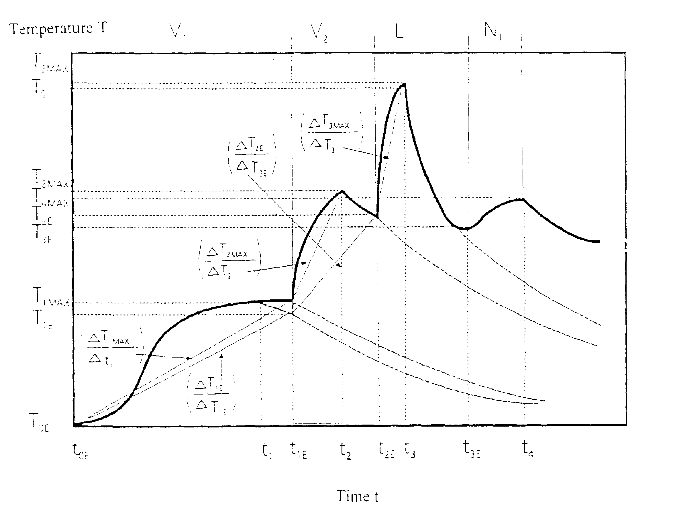
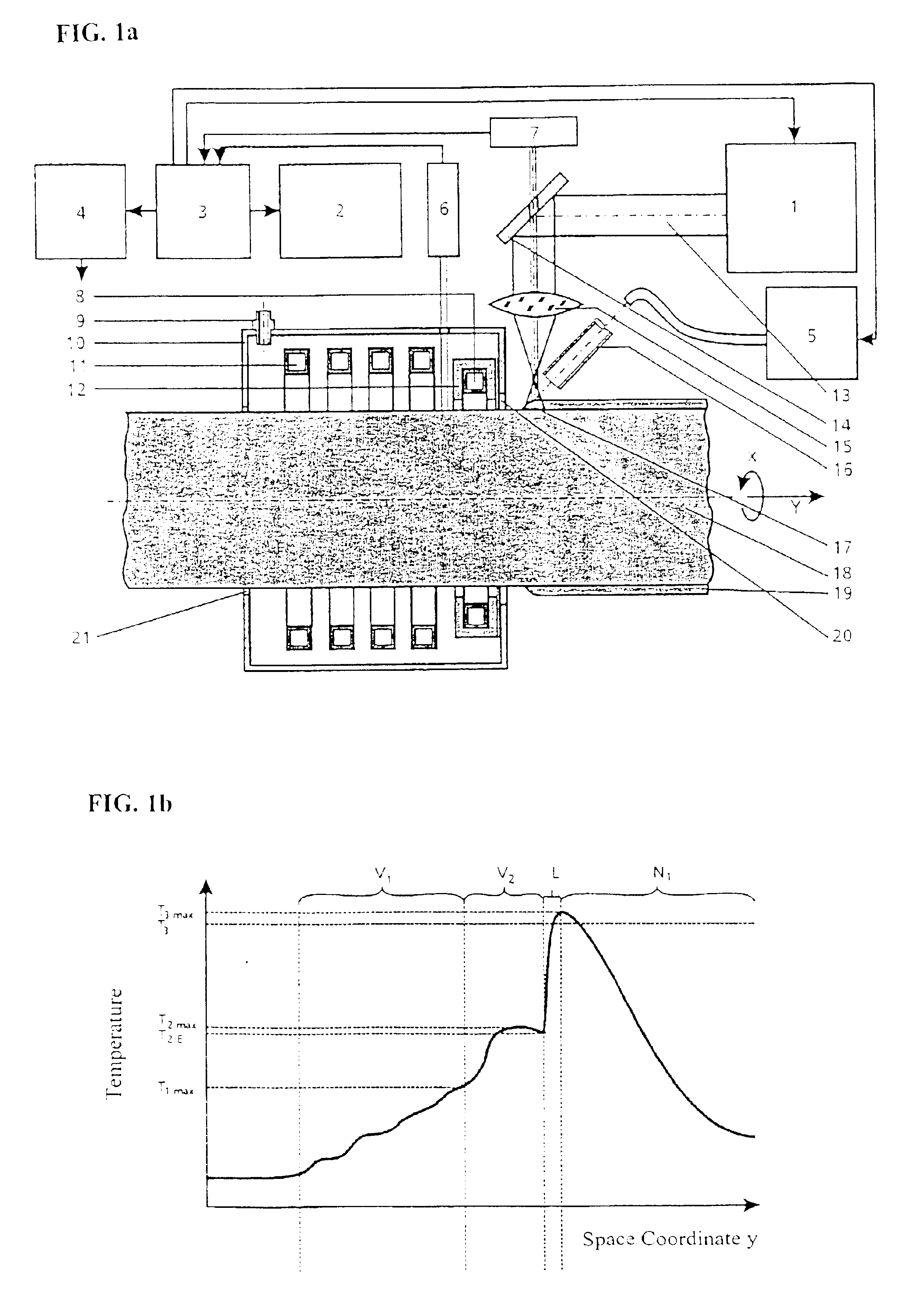
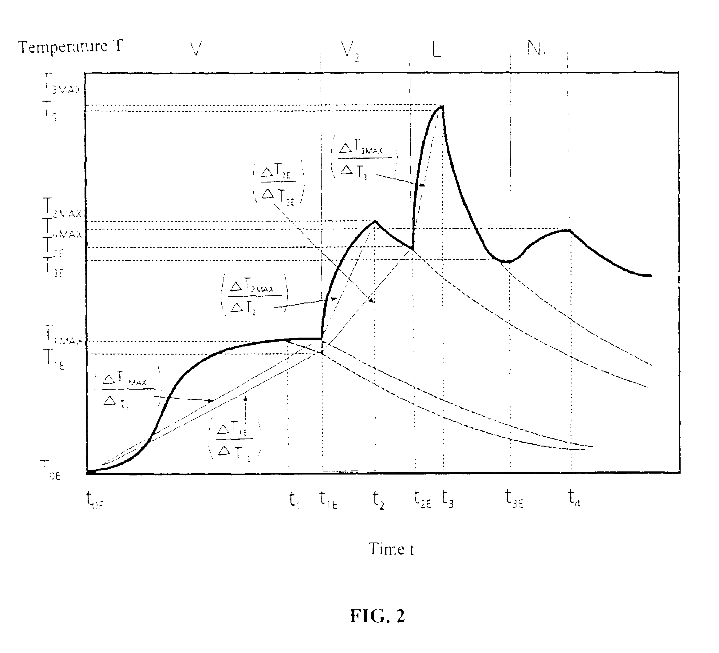
The process control that is most favorable in energy terms results, when the additive is added in molten form. This variant is possible because, due to the very high temperature of the preheating cycle V2 according to the invention, it is possible to control the process cycle L such that, even at high feed rates, a metallic bonding of the melt to the substrate material is produced and fusion defects are avoided.

Problems solved by technology

For a number of applications, in particular those with large surfaces subject to wear stress, however, there is the negative effect that the cost of the layers produced by laser build-up welding is too high.
The reason for this drawback is that the specific costs of providing energy are much higher with a laser than with other conventional energy sources such as, e.g., TIG or plasma torch.
A second drawback is that the layers produced by means of the laser build-up welding, i.a., tend more towards crack formation than those produced by conventional methods, if a change is made to harder and thus less ductile coating materials or martensitic hardenable substrate materials.
The reason for this drawback is due to the fact that the very intensive energy input aimed at and realized with the laser action is associated with very high power densities which lead to large temperature gradients and thus to such high transient thermal tensions in the cooling phase that cannot be tolerated by a number of coating and substrate materials without cracking.
Moreover, the specific energy provision costs for the coupled inductive energy are at least one order of magnitude lower than for laser energy.
Accordingly, an unsteady preheating temperature field results with a maximum that is shifted somewhat towards the laser beam and runs before the temperature field produced by the laser beam.
The drawback of the process is that the feed rate cannot be increased to the extent that should actually be possible from estimates of the energy balance.
The reason for this is that the temperature fields that can be produced with an inductor (lower energy transmission effectiveness through use of the inductive outer field) or with an oxygen acetylene burner in the claimed arrangement cannot be adequate adapted to the requirements of laser alloying or laser build-up welding.
Moreover, the temperature of the preheating temperature field at the time the laser beam passes has dropped so much that no substantial effect can result regarding an increase of the feed rate.
However, it has proven to be a drawback that the pretreatment in the furnace is very complicated, lengthy and expensive.
Moreover, it has a detrimental effect that the components have to be transported, positioned and clamped while in a hot condition.
The reason for both drawbacks is that the parts have to be thoroughly heated in a separate device.
A further drawback is that, due to the increasing oxidation of the component, the preheating temperature is limited to approximately 600° C. The possibilities of a further increase in speed have thus also been exhausted.
A higher preheating temperature affects the quality of the alloyed layer in that oxide inclusions or pores occur which reduce the mechanical load capacity of the layers and their wear resistance.
However, due to stochastic melting bath turbulences, it cannot be ensured that all slag particles or metal oxides rise to the melting bath surface.
These coats are therefore not suitable for stresses in which very high surface pressings or cyclical tensions occur.
A considerable drawback of the process is that evidently only very slight increases in the process velocity could be achieved.
An increase in the preheating temperature to higher temperature values for greater critical ranges, such as are necessary for conducting this process on larger components, is not possible due to the oxide and scale formation that greatly increases with the temperature.
Another drawback of the process is that it is difficult to apply to larger and in particular intricately formed workpieces.

Method used


Image

  • Process for producing wear-resistant surface layers
  • Process for producing wear-resistant surface layers
  • Process for producing wear-resistant surface layers

Examples


example 2

A steam generator pipe (cf. (18) in FIG. 4) is to be used in a corrosive environment. Since it is uneconomical to manufacture the whole pipe of an expensive corrosion-resistant material, it should be made of the cost-effective St52-3 structural steel and be protected with the material NiCr21Mo9Nb by a build-up welding process. Due to the low feed rate, the conventional build-up welding processes insert too much and undefined heat, so that it is difficult to keep the mixture at the necessary low level. However, laser build-up welding is uneconomical because the feed rate is too low.

To resolve this, a special embodiment of the arrangement according to the invention is used which is characterized by its particular simplicity (see FIG. 4). The inductive preheating is realized by an inductor I12b which contains the two inductor branches 11 and 8 which form the two inductors 11 and 12. While the inductor I1 11 is arranged in the direction {overscore (y)} of the longitudinal feed of the pi...


PUM

PropertyMeasurementUnit
angle of wrapaaaaaaaaaa
temperatureaaaaaaaaaa

Abstract

Process for the effective production of very wear-resistant layers in the thickness range of 0.2 to approx. 3 mm by way of inductively supported surface layer modification. It can be used particularly advantageously for the protection of components of hardenable steels and cast iron with abrasive, corrosive, high-temperature corrosive or mineral sliding wear loading. With the process according to the invention a local two-stage inductive short-time preheating takes place directly before the surface layer coating. Due to the invention it is possible to coat even hardenable steels or other materials difficult to coat without cracking. Furthermore, even harder coating materials susceptible to cracking which provide better wear-resistances can be used. In addition, process speeds and surface coating performances can be achieved that are higher by a factor of 10 compared with conventional laser build-up welding. This abstract is neither intended to define the invention disclosed in this specification nor intended to limit, in any manner, the scope of the invention.

Description

CROSS-REFERENCE TO RELATED APPLICATIONSThe present application is based upon German Priority Application No. 101 37 776.2, filed Aug. 2, 2001, the disclosure of which is hereby expressly incorporated by reference hereto and the priority of which is hereby claimed under 35 U.S.C. §119.BACKGROUND OF THE INVENTION1. Field of the InventionThe invention relates to a process for the effective production of highly wear-resistant layers on inductively heatable workpieces. Articles for which their application is possible and useful, are a number of components subjected to abrasive, corrosive, adhesive or sliding wear, preferably made of steel, but also of cast iron or aluminum or titanium alloys. The invention is particularly advantageously applicable to all hardenable steels or steels susceptible to cracking, such as, e.g., heat-treatable steels, tool steels, cold work steels, bearing steels and hardenable sorts of gray iron. Components for which this invention can be used are, e.g., motor ...

Claims


Application Information

Patent Timeline
Patent Type & Authority Patents(United States)
IPC IPC(8): B23K26/42B23K10/02B23K26/34B23K26/00C21D1/09F15B15/14F15B15/00B23K35/32B23K35/24C21D1/10B23K26/32B23K26/342B23K26/60
CPCB23K10/027C21D1/42B23K26/421C21D1/09F15B15/1428F15B15/1457B23K26/3206B23K26/345B23K35/0222B23K35/0255B23K35/0244C21D9/50B23K26/34B23K35/327B23K2201/04B23K2203/04C21D1/10B23K2201/06B23K2201/14B23K2201/20F28F19/06B23K26/32B23K26/342B23K26/60B23K26/70B23K2101/04B23K2101/06B23K2101/14B23K2101/20B23K2103/04B23K2103/50Y02P10/25
Inventor BRENNER, BERNDTFUX, VOLKER
Owner FRAUNHOFER GESELLSCHAFT ZUR FOERDERUNG DER ANGEWANDTEN FORSCHUNG EV
Learn More