Ultrasonic transducer, biological sensor, and method for manufacturing an ultrasonic transducer

a technology of ultrasonic transducers and biological sensors, which is applied in the field of ultrasonic transducers, biological sensors, and methods for manufacturing ultrasonic transducers, can solve the problems of uneven thickness of diaphragms, variance in the drive characteristics of ultrasonic transducers, and etching all the way down to the diaphragm, etc., to achieve stable drive characteristics, easy and accurate formation, and the effect of more accurate operation

Active Publication Date: 2012-12-06
SEIKO EPSON CORP
View PDF2 Cites 31 Cited by
  • Summary
  • Abstract
  • Description
  • Claims
  • Application Information

AI Technical Summary

Benefits of technology

[0022]With the above described aspect of the present invention, after the piezoelectric element has been formed on the first face of the support film in the piezoelectric element formation step, the resin substrate is formed on the second face of the support film in the resin substrate formation step, and the opening is formed in the resin substrate in the opening formation step. With an ultrasonic transducer formed by this manufacturing method, an opening can be formed easily and accurately, and an ultrasonic transducer with stable drive characteristics can be manufactured, by irradiating with light in the opening formation step.
[0023]Also, by affixing the reinforcing substrate to the support film, curving of the support film can be prevented in the formation of the resin substrate on the support film, or in the formation of the opening in the resin substrate, and the formation of the resin substrate and the opening can be carried out more accurately.

Problems solved by technology

When a diaphragm is thus formed by etching a substrate, the thickness of the diaphragm may be uneven due to differences in the etching rate.
Also, with a diaphragm is formed by etching, some of the silicon substrate may remain on the diaphragm if the etching duration is short, and over-etching may result in etching all the way down to the diaphragm if the etching lasts too long.
If the diaphragm thickness thus ends up being uneven, there may also be variance in the drive characteristics of the ultrasonic transducer.
Specifically, when an opening is formed by subjecting a substrate provided with a support film to etching with an inductively coupled plasma (ICP) or the like, for example, the portion that functions as the support film may also end up being etched away, and the thickness of the support film may be uneven.

Method used


Image

  • Ultrasonic transducer, biological sensor, and method for manufacturing an ultrasonic transducer
  • Ultrasonic transducer, biological sensor, and method for manufacturing an ultrasonic transducer
  • Ultrasonic transducer, biological sensor, and method for manufacturing an ultrasonic transducer

Examples


first embodiment

Action and Effect of First Embodiment

[0077]The following effects are obtained with the above ultrasonic transducer 10.

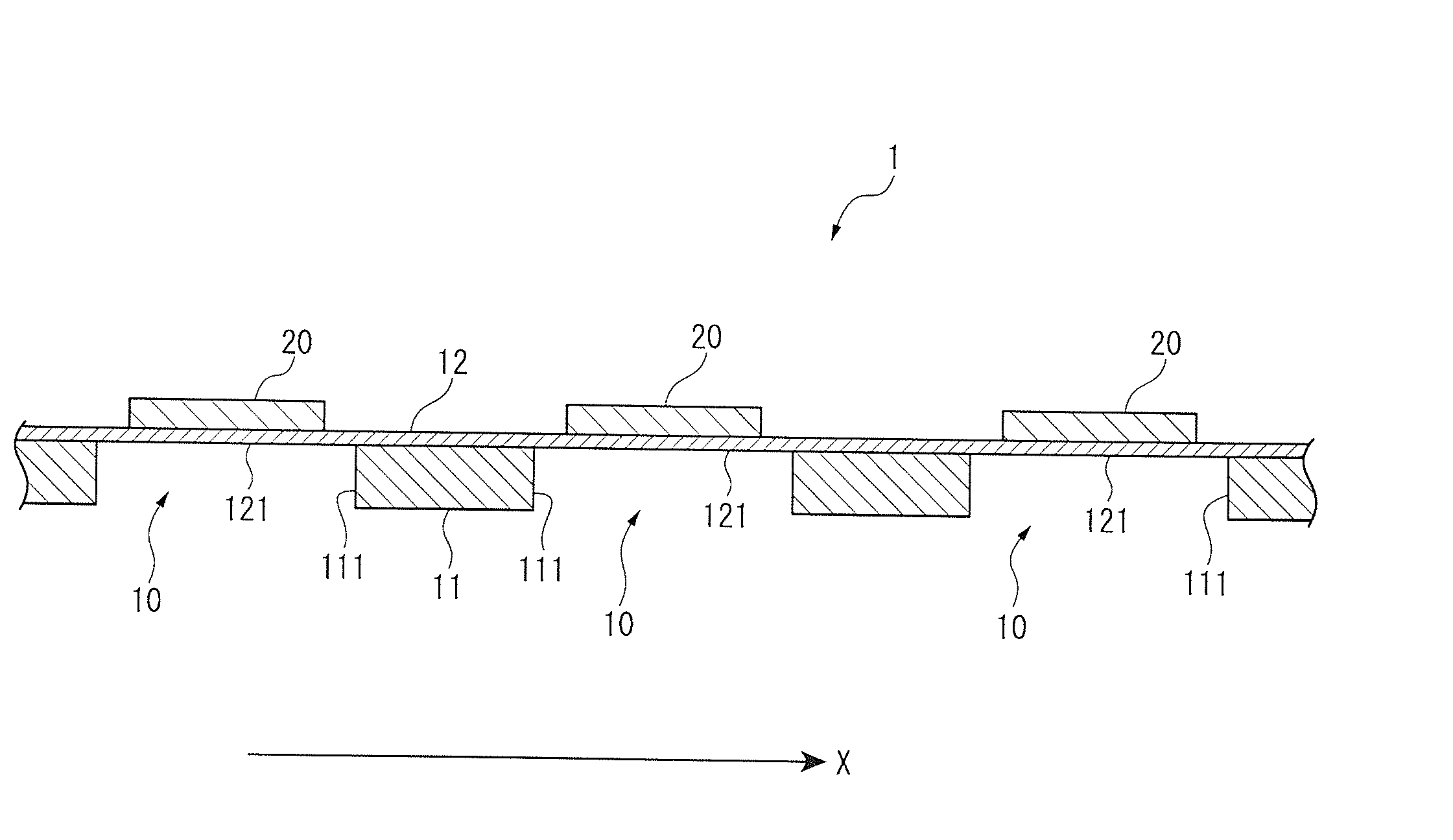
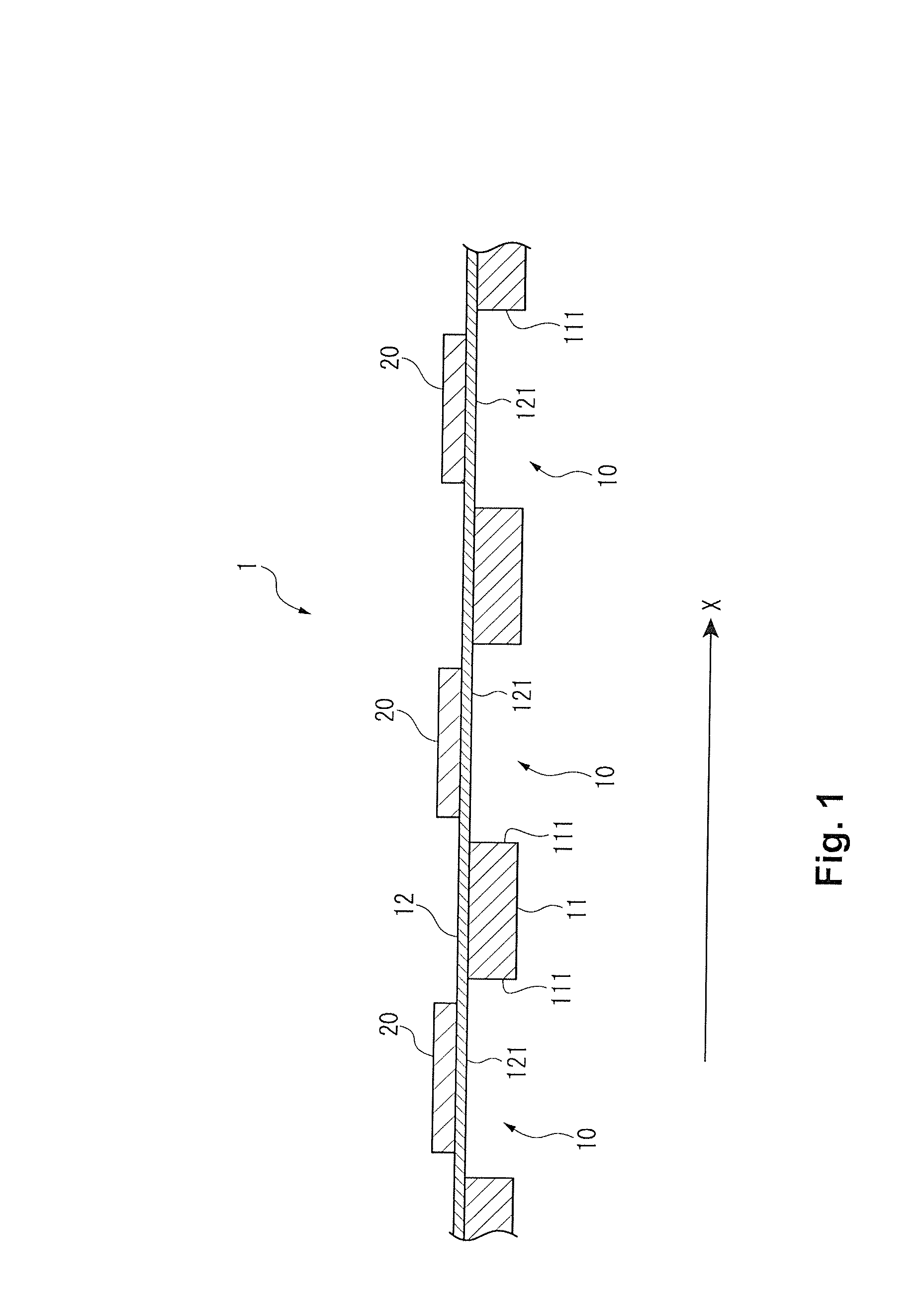
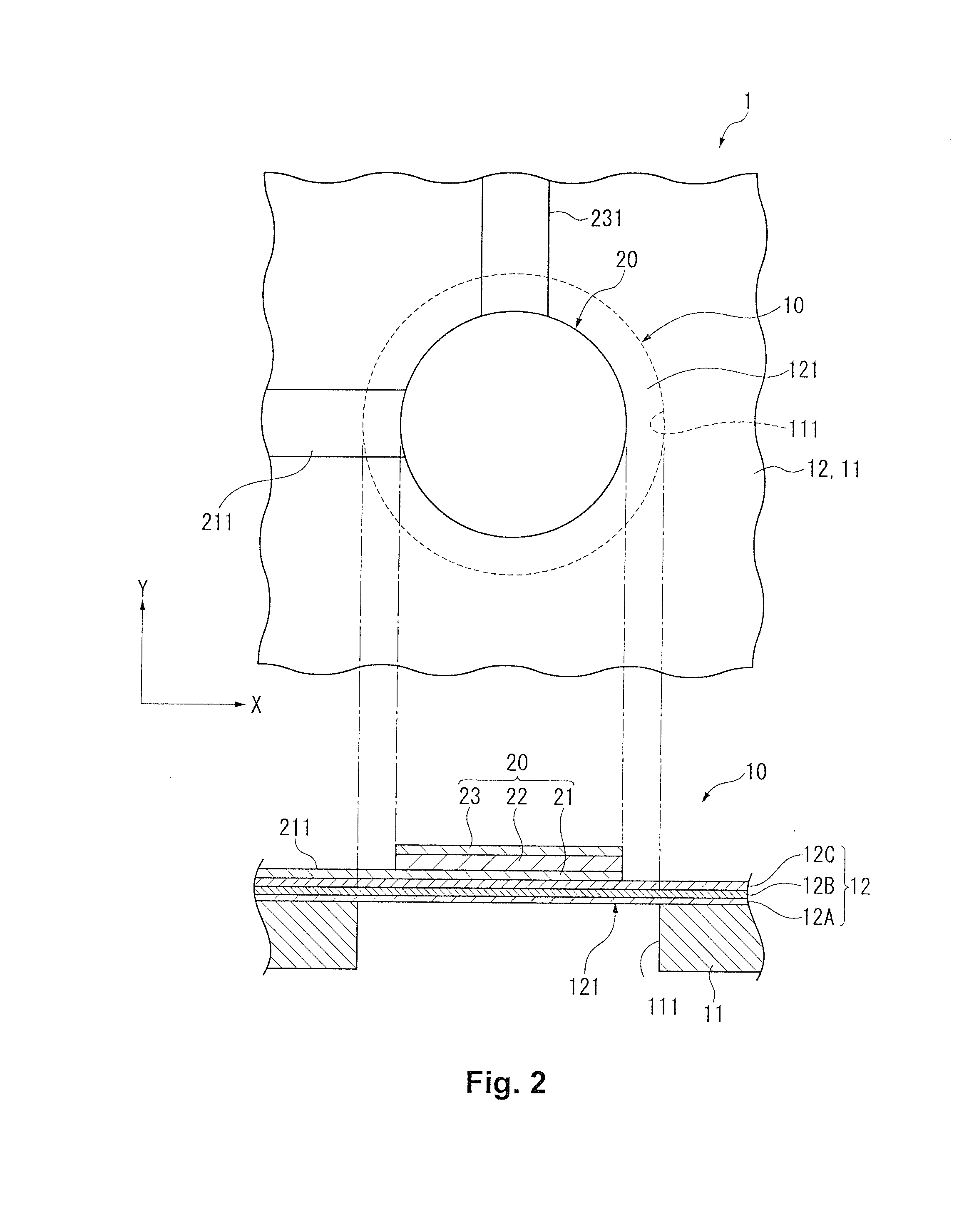
[0078]The ultrasonic transducer 10 in this embodiment comprises the photosensitive film 11 in which the opening 111 is formed, the support film 12 equipped with the membrane 121 that blocks off the opening 111 of the photosensitive film 11, and the piezoelectric element 20 provided on the membrane 121 of the support film 12. With this ultrasonic transducer 10, since the photosensitive film 11 is flexible, and the support film 12 is thick enough to vibrate the membrane 121, the structure is more pliant than when the support that supports the support film 12 is formed by a silicon substrate or another such semiconductor substrate. Therefore, the ultrasonic transducer 10 is flexible and can be freely deformed into a planar shape that matches the measurement object.

[0079]Also, in the manufacture of the ultrasonic transducer 10 having the photosensitive film 11, since the...

second embodiment

Action and Effect of Second Embodiment

[0093]The biological sensor 106 of the above-mentioned biological test apparatus 100 comprises the sensor array 1 described in the first embodiment above, and the contact layer 107 provided on the support film 12 of the sensor array 1. Here, as discussed above, since the sensor array 1 is flexible and able to deform into any planar shape, when the contact layer 107 comes into contact with the skin of the organism and is elastically deformed, the planar shape of the sensor array 1 also deforms according to the deformation of the contact layer 107. Accordingly, the planar shape of the sensor array 1 is a shape that matches the skin of the organism. With a constitution such as this, since the distance between the ultrasonic transducers 10 and the skin is uniform, the time it takes for the ultrasonic waves generated from the ultrasonic transducers 10 to reach the organism is the same for all of the waves, and this reduces measurement error. Also, if...

modification examples

[0094]The present invention is not limited to the embodiments given above, and modifications, improvements, and so forth that still allow the object of the present invention to be achieved are encompassed by the present invention.

[0095]For instance, in the above embodiments, an example was given in which the flexible photosensitive film 11 was used as a resin substrate, but this is not the only option. In application to the biological sensor in the second embodiment, for example, it is preferable if the photosensitive film 11 is flexible so as to deform the sensor array 1 according to the measurement position on the organism, but as long as the planar shape of the sensor array 1 is fixed, a resin substrate with greater hardness may be used.

[0096]Also, in the above embodiments, in the opening formation step S6 a positive photosensitive resin was used as the photosensitive film 11, and the location where the opening 111 was to be formed was irradiated with ultraviolet rays to remove t...


PUM

PropertyMeasurementUnit
diameteraaaaaaaaaa
thicknessaaaaaaaaaa
thicknessaaaaaaaaaa

Abstract

An ultrasonic transducer includes a resin substrate, a support film and a piezoelectric element. The resin substrate has an opening. The support film blocks off the opening in the resin substrate. The piezoelectric element is disposed on the support film in a region that blocks off the opening in plan view from a thickness direction of the support film. The piezoelectric element includes a lamination of a lower electrode, a piezoelectric body, and an upper electrode.

Description

CROSS-REFERENCE TO RELATED APPLICATIONS[0001]This application claims priority to Japanese Patent Application No. 2011-122158 filed on May 31, 2011. The entire disclosure of Japanese Patent Application No. 2011-122158 is hereby incorporated herein by reference.BACKGROUND[0002]1. Technical Field[0003]The present invention relates to an ultrasonic transducer that sends and / or receives ultrasonic waves, as well as a biological sensor equipped with said ultrasonic transducer, and a method for manufacturing said transducer.[0004]2. Related Art[0005]An ultrasonic transducer that sends and receives ultrasonic waves has been known before now (see Japanese Laid-Open Patent Application Publication No. 2003-304595, for example).[0006]The diaphragm-type transducer (ultrasonic transducer) discussed in the above mentioned publication comprises a silicon substrate in which an opening is formed, an insulating layer and vibrating layer laminated on this substrate so as to block off this opening, and ...

Claims


Application Information

Patent Timeline
Patent Type & Authority Applications(United States)
IPC IPC(8): H01L41/04H01L41/22
CPCH01L41/0973H01L41/312B06B1/0651A61B8/0891Y10T29/42A61B8/4455G01N29/36H01L41/23A61B8/4227Y10T29/49005Y10T29/49126H10N30/2047H10N30/01H10N30/072H03H3/02H03H3/04H03H2003/045H10N30/02
Inventor NAKAMURA, TOMOAKISUZUKI, HIRONORI
Owner SEIKO EPSON CORP
Why Eureka
Try Eureka