Vibration actuator, and lens barrel and camera provided with the vibration actuator

a technology of vibration actuator and lens barrel, which is applied in the direction of printers, instruments, camera focusing arrangement, etc., can solve the problems of high production cost, and achieve the effect of simple configuration and stable drive characteristics

Inactive Publication Date: 2011-05-05
NIKON CORP
View PDF4 Cites 3 Cited by
  • Summary
  • Abstract
  • Description
  • Claims
  • Application Information

AI Technical Summary

Benefits of technology

[0018]According to the present invention, it is possible to provide a vibration actuator having stable drive characteristics, and a lens barrel and a camera equipped with such a vibration actuator in a simple configuration.

Problems solved by technology

However, the abovementioned prior art has a problem in that requires circuits and the like for detection and control, and thus the configuration thereof becomes complex, a result of which production cost is high.

Method used


Image

  • Vibration actuator, and lens barrel and camera provided with the vibration actuator
  • Vibration actuator, and lens barrel and camera provided with the vibration actuator
  • Vibration actuator, and lens barrel and camera provided with the vibration actuator

Examples


Embodiment Construction

[0034]An embodiment of the present embodiment is explained hereinafter with reference to the drawings. It should be noted that the following embodiment is described by employing an ultrasonic motor 10 using vibration in the ultrasonic range as a vibration actuator.

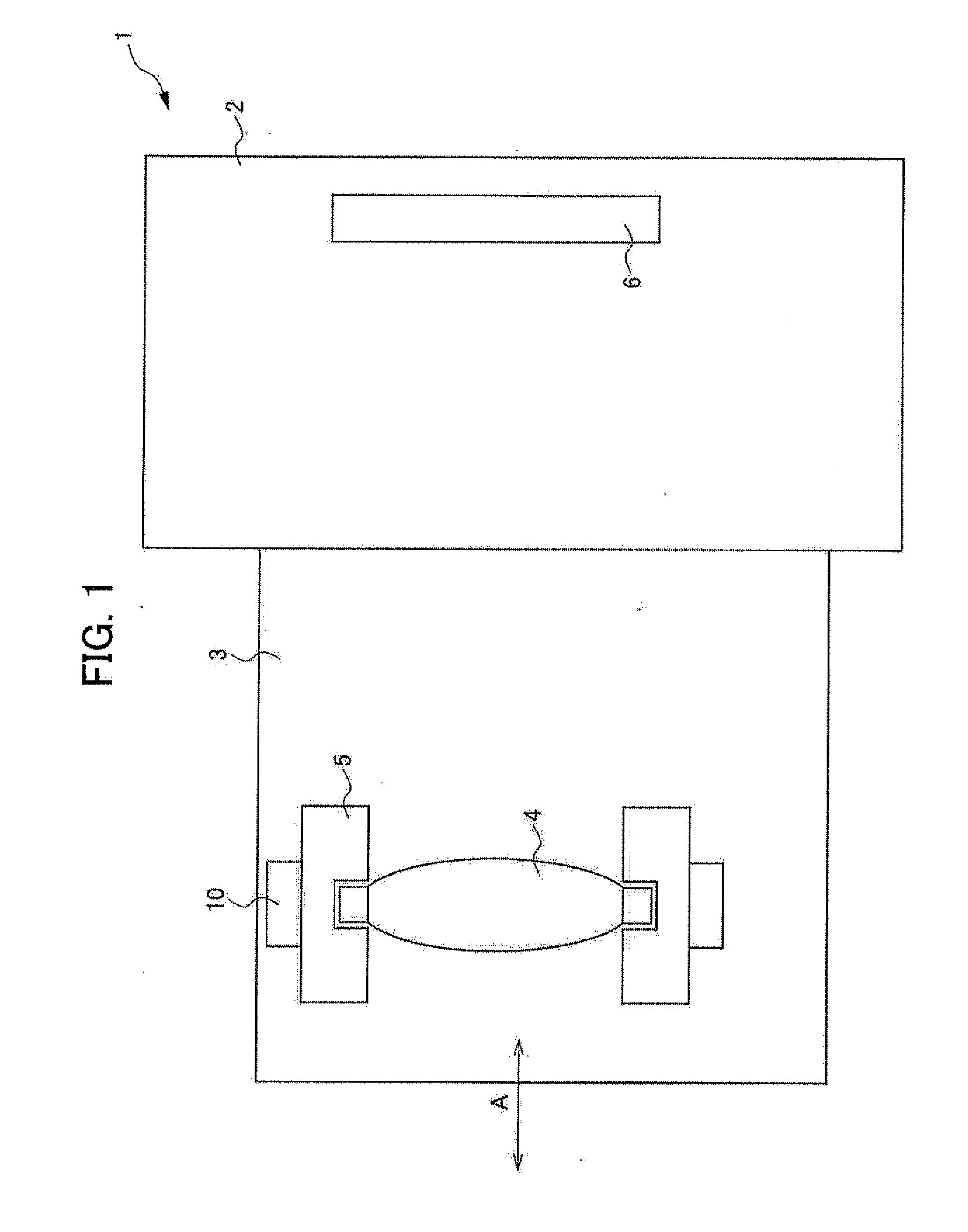
[0035]FIG. 1 is a diagram illustrating a camera 1 having an ultrasonic motor 10 according to the present embodiment. The camera 1 is provided with a camera body 2 having an imaging element 6, and a lens barrel 3. The lens barrel 3 is an interchangeable lens that can be detached from the camera body 2. It should be noted that, although the present embodiment shows an example in which the camera 1 has the lens barrel 3 that is an interchangeable lens, the present invention is not limited thereto and, for example, the lens barrel 3 may be a lens barrel that is integrated with the camera body.

[0036]The lens barrel 3 is provided with a lens 4, a cam barrel 5, an ultrasonic motor 10, and the like. The ultrasonic motor 10 is a su...


PUM


Abstract

Provided is a vibration actuator having stable drive characteristics, and a lens barrel and a camera which are provided with such vibration actuator. The vibration actuator of the present invention is provided with: a relatively moving member, which is brought into pressurized contact with a vibrating member, and moves relative to the vibrating member by vibration of the vibrating member; a pressure member which brings the vibrating member and the relatively moving member into pressurized contact with each other; and a magnetic force generating section which adjusts the pressurizing force of the pressure member by a magnetic force.

Description

TECHNICAL FIELD[0001]The present invention relates to a vibration actuator, and a lens barrel and a camera provided with the vibration actuator.BACKGROUND ART[0002]A vibration actuator includes a vibrating body. The vibrating body includes an elastic body and an electromechanical conversion element. The vibration actuator causes the electromechanical conversion element to extend and contract by way of a drive signal and uses this extension and contraction to generate a progressive vibration wave (hereinafter, referred to as progressive wave) on a driving face of the elastic body. This progressive wave causes an elliptical motion, thereby driving a relatively moving member in pressurized contact with the wave crests of the elliptical motion. In such a vibration actuator, the drive characteristics change under the high temperature or low temperature environment from a state at ordinary temperature.[0003]Technology has been disclosed which provides a sensor electrode with a piezoelectr...

Claims


Application Information

Patent Timeline
Patent Type & Authority Applications(United States)
IPC IPC(8): H04N5/228
CPCG02B7/08H02N2/163G02B27/646G02B7/102E02F9/221G03B13/34G03B3/10
Inventor SATO, TAKAHIRO
Owner NIKON CORP
Why Eureka
Try Eureka