Balance shaft structure

a technology of balance shaft and shaft shaft, applied in the direction of mechanical equipment, machine/engine, vibration suppression adjustment, etc., can solve problems such as complicated operations

Active Publication Date: 2021-01-12
HONDA MOTOR CO LTD
View PDF15 Cites 0 Cited by
  • Summary
  • Abstract
  • Description
  • Claims
  • Application Information

AI Technical Summary

Benefits of technology

[0006]An object of the present invention is to provide a balance shaft structure capable of easily regulating a scissors mechanism in position in an axial direction.
[0030]According to the above configuration, the first regulating portion can be formed easily and accurately.

Problems solved by technology

That is, to regulate the scissors mechanism in position in the axial direction with the conventional balance shaft structure, it is required to fasten three bolts while sandwiching three spacers and three washers, resulting in complicated operations.

Method used


Image

  • Balance shaft structure
  • Balance shaft structure

Examples


Embodiment Construction

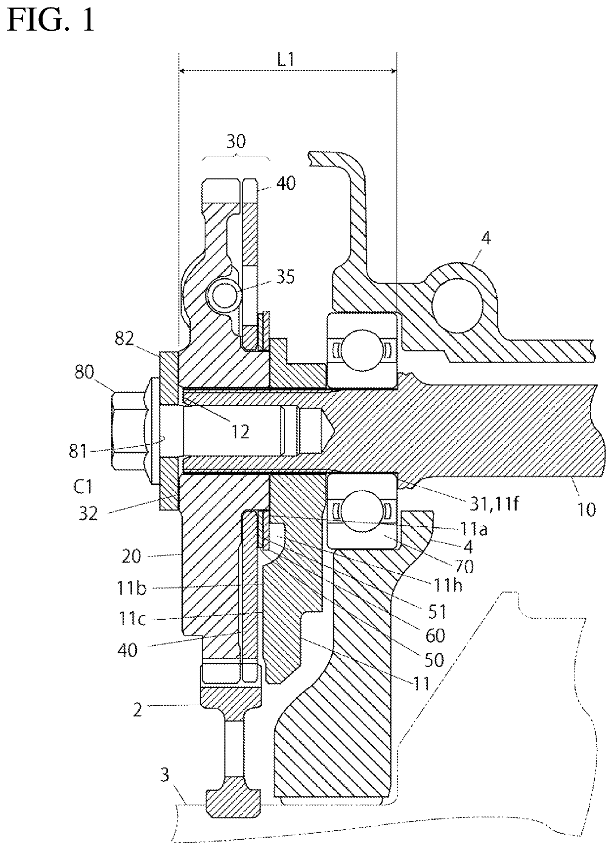
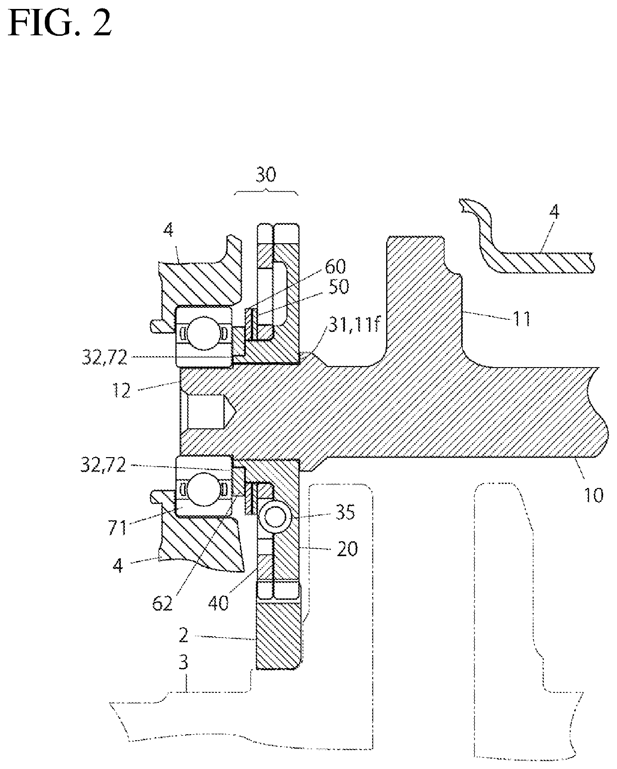
[0033]In the following, description will be provided on embodiments of a balance shaft structure of the present invention with reference to the drawings. In each drawing, the same reference sign is given to the same or corresponding component.

[0034]As illustrated in FIG. 1, a balance shaft structure of an embodiment includes a balance shaft 10 provided with a balance weight 11, a driven gear 20 to rotate the balance shaft 10 by being engaged with a drive gear 2, and a scissors mechanism 30 to reduce backlash between the drive gear 2 and the driven gear 20.

[0035]The scissors mechanism 30 is a mechanism, whose position in an axial direction is regulated, including a scissors gear 40 and an axially urging member 50 to urge the scissors gear 40 toward the driven gear 20 in the axial direction.

[0036]The balance shaft structure of the present embodiment includes a first regulating portion 31 that regulates an axially inner position of the scissors mechanism 30, the first regulating portio...


PUM


Abstract

A balance shaft structure includes a balance shaft including a balance weight, a driven gear to rotate the balance shaft by being engaged with a drive gear, a scissors mechanism, whose position in an axial direction is regulated, including a scissors gear to reduce backlash between the drive gear and the driven gear and an axially urging member to urge the scissors gear toward the driven gear in the axial direction, a first regulating portion to regulate an axially inner position of the scissors mechanism, and a second regulating portion fixed to the balance shaft on a side close to the shaft end part of the balance shaft beyond the first regulating portion and configured to regulate an axially outer position of the scissors mechanism.

Description

BACKGROUND1. Technical Field[0001]The present invention relates to a balance shaft structure.2. Description of the Background[0002]Traditionally, as disclosed, for example, in Patent Literature 1, there has been known a balance shaft structure that includes a balance shaft provided with a balance weight, a driven gear to rotate the balance shaft by being engaged with a drive gear, and a scissors mechanism, whose position in an axial direction is regulated, including a scissors gear (backlash gear) to reduce backlash between the drive gear and the driven gear and an axially urging member (disc spring) to urge the scissors gear toward the driven gear in the axial direction.CITATION LISTPatent Literature[0003]Patent Literature 1: Japanese Patent Application Laid-open No. 2001-271883BRIEF SUMMARY[0004]According to the conventional balance shaft structure, the scissors mechanism is regulated in position in the axial direction as follows. First, three washers are abutted to corresponding ...

Claims


Application Information

Patent Timeline
Patent Type & Authority Patents(United States)
IPC IPC(8): F02B75/06F16F15/26F16F15/28
CPCF16F15/265F16F15/283F16F15/26F16F15/264F16H55/18
Inventor TANAKA, KAZUMAKATO, NARUMIOKADA, NOZOMIITO, JUNNOSUKE
Owner HONDA MOTOR CO LTD
Why Eureka
Try Eureka