Liquid crystal display device and method for driving liquid crystal display device

a display device and liquid crystal technology, applied in the field of liquid crystal display devices, can solve the problems of deterioration of images, blur in moving objects, slow response time of holding display devices, etc., and achieve the effect of high image quality

Active Publication Date: 2005-09-15
SHARP KK
View PDF18 Cites 31 Cited by
  • Summary
  • Abstract
  • Description
  • Claims
  • Application Information

AI Technical Summary

Benefits of technology

[0017] The present invention is accomplished in consideration of the problem mentioned above and an object of the pr...

Problems solved by technology

Thus, in general, the holding type display device has a slow response time.
Therefore, the holing type display device has a problem in that deterioration of an image, for example, a blur in a moving object, occurs especially when it displays a moving image.
However, the display device disclosed in Tokukai 2003-66918, which enables a response waveform to raise abruptly from a black level by the fast-response screen image, cannot display a correct screen image if the blanking data has not written in completely.
Therefore, it is impossible to display a gray scale of the...

Method used


Image

  • Liquid crystal display device and method for driving liquid crystal display device
  • Liquid crystal display device and method for driving liquid crystal display device
  • Liquid crystal display device and method for driving liquid crystal display device

Examples


embodiment 1

[0041] A first exemplary embodiment (exemplary embodiment 1) of the present invention is explained as follows, referring to drawings. In the exemplary embodiment, it is put that a video signal is a 60 Hz progressive signal.

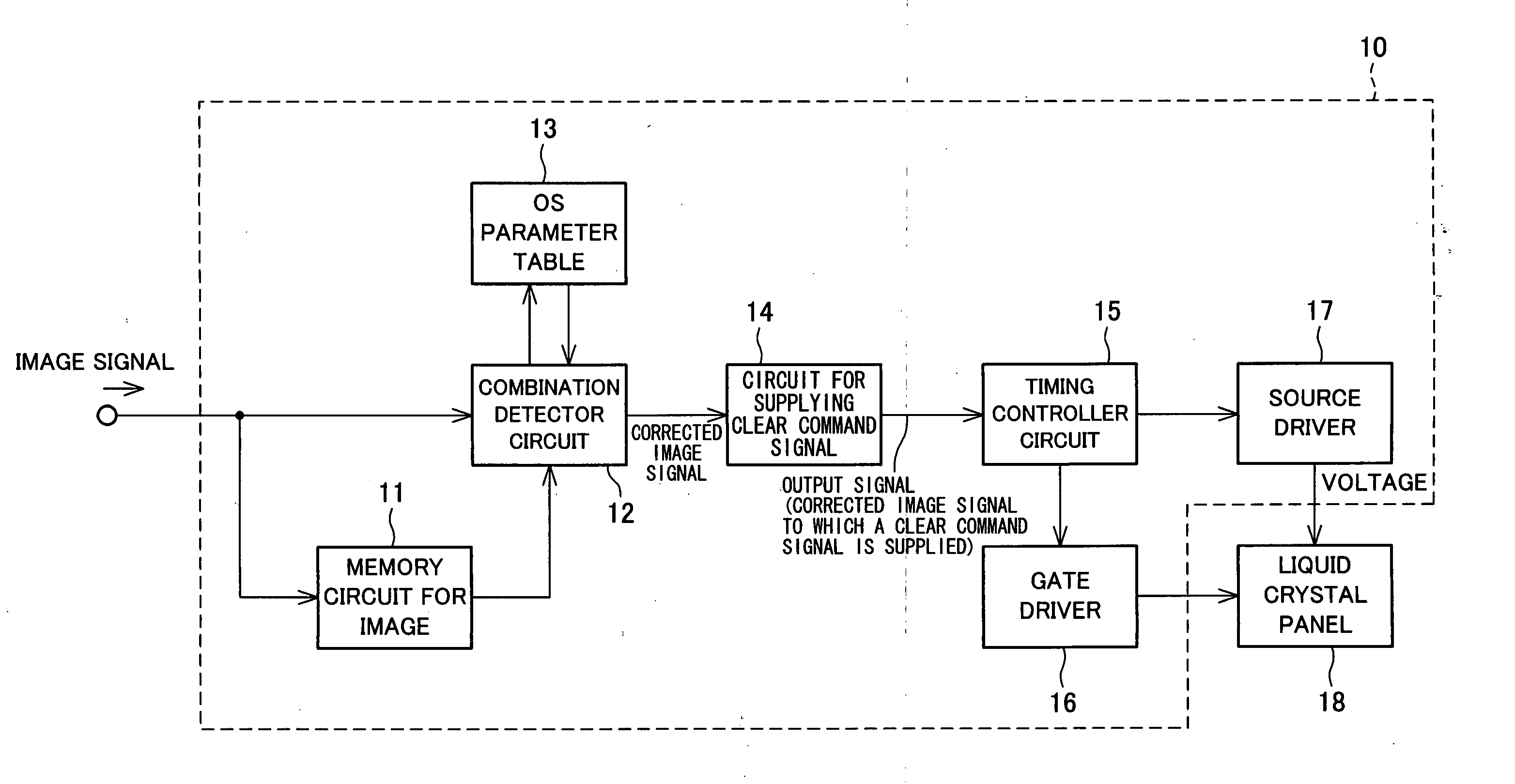
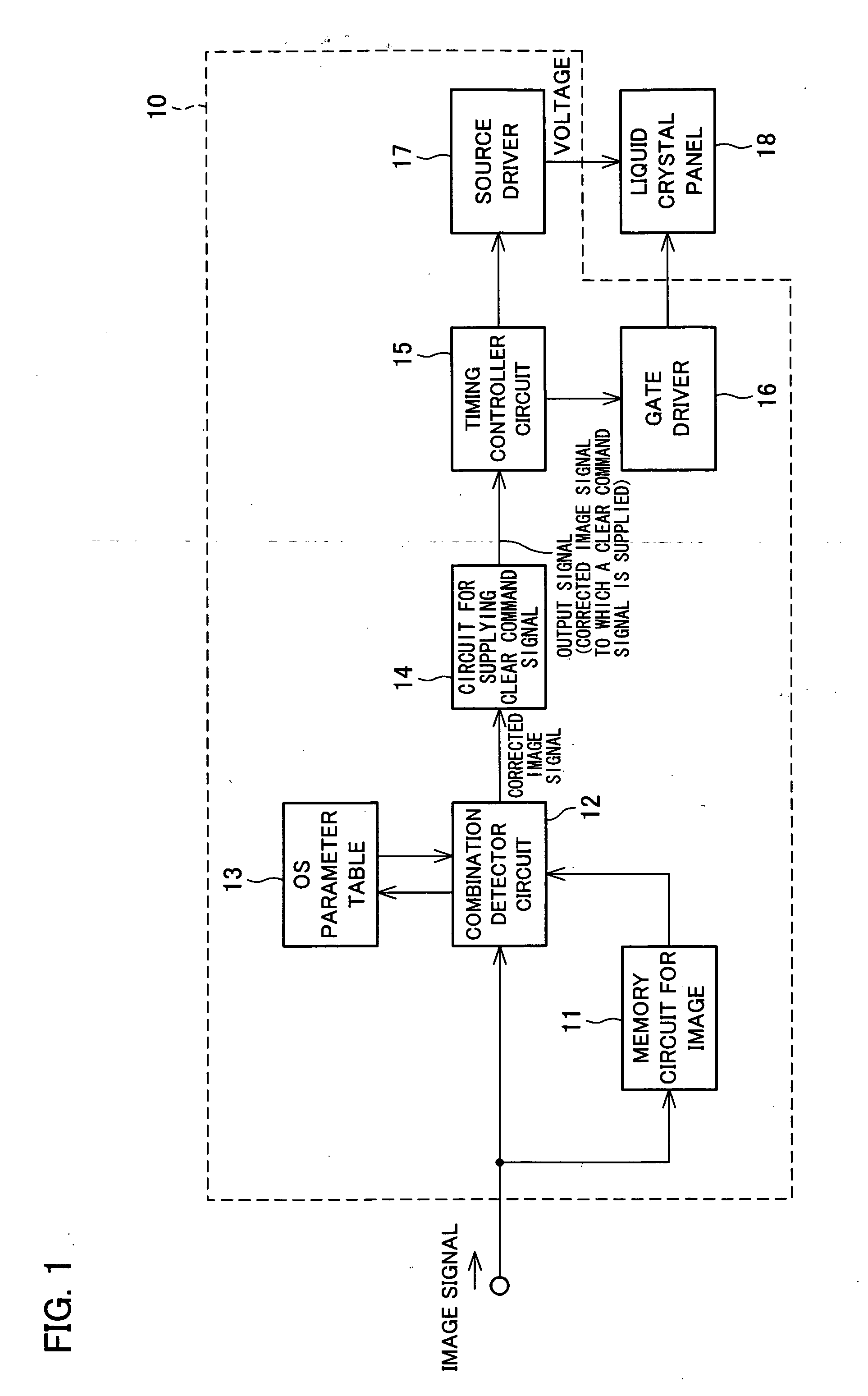
[0042]FIG. 1 is a schematic diagram of an arrangement of a liquid crystal display device according to the exemplary embodiment of the present invention. In FIG. 1, sections unnecessary for explanation are omitted from the diagram.

[0043] The liquid crystal display device embodying the present invention includes a driving circuit 10 and a liquid crystal panel 18.

[0044] The driving circuit 10 includes a memory circuit 11 for storing an image therein, a combination detector circuit 12, an overshoot parameter table (an OS parameter table) 13, a circuit 14 for supplying a clear command signal, a timing controller circuit 15, a gate driver 16, and a source driver 17. The driving circuit 10 generates an image signal of an image to be displayed and provides the image si...

embodiment 2

[0076] A second exemplary embodiment (exemplary embodiment 2) of the present invention has the same arrangement as the exemplary embodiment 1 except the method of setting an OS parameter table which is looked up by a combination detector circuit 12. How to set the OS parameter table in this exemplary embodiment explained as follows.

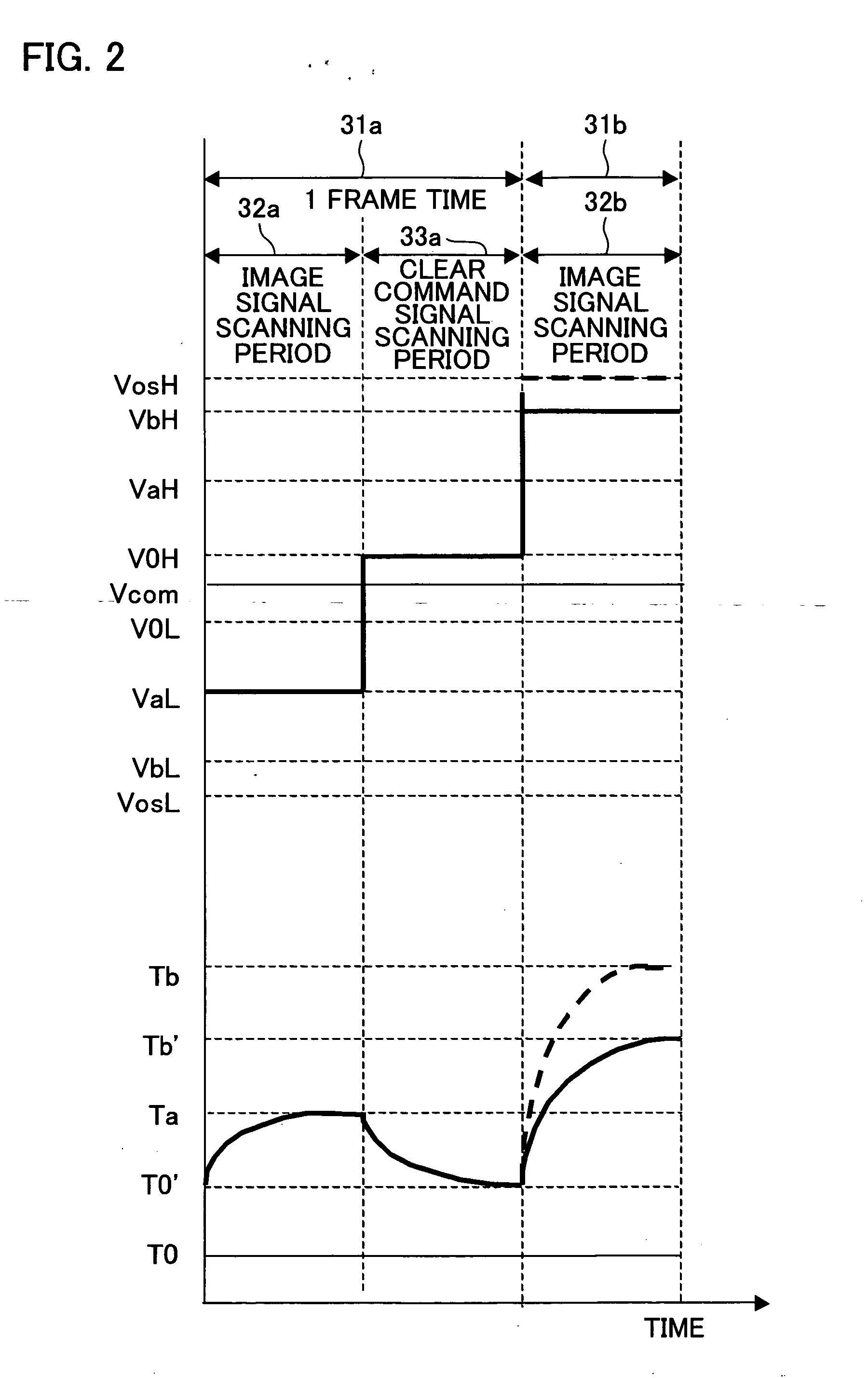
[0077] As explained above, in one display, voltage Vos (illustrated in FIG. 2), which is given to a pixel, is determined depending on peak transmittance Ta at a steady state and peak transmittance Tb at a steady state. In this exemplary embodiment, voltage out of voltage range corresponding to a gray scale level of an image signal is used as the voltage Vos.

[0078]FIG. 8 schematically illustrates relation between transmittance and voltage when a rectangular pulse of a constant voltage is applied to a liquid crystal. FIG. 8 illustrates how the transmittance of the liquid crystal changes in relation to a change in an applied voltage. As illustrated in FIG....

embodiment 3

[0083] A third exemplary embodiment of the present invention employs a different method of setting a gamma value of a liquid crystal panel. Thus, the method is explained as follows, discussing a case in which a desirable gamma value is 2.2 by way of example.

[0084] In this exemplary embodiment, when a preceding image signal and a present image signal take the same gray scale level (i.e., particularly when a still image is displayed), a corrected image signal is not generated but an input signal is outputted as it is.

[0085] In order to set the gamma value of the liquid crystal panel, first, voltages for all the 256 gray scale levels from the gray level 0 (black) to the gray level 255 (white) are temporally predetermined at voltages ranging between 1.6V and 7.1V. Then an applied voltage corresponding to the image signal is adjusted so that the gamma value of 2.2 is taken for gray scale / transmittance characteristics concerning the gray scale level of the image signal and the peak tran...


PUM


Abstract

A liquid crystal display device, including (a) a liquid crystal panel for carrying out display by voltage application to pixels, each of which has a liquid crystal layer, and (b) a driving circuit for applying, within one frame time, (i) voltages that respectively correspond with image signals and (ii) a voltage that corresponds with a clear command signal, to the pixels of said liquid crystal panel, is arranged such that said driving circuit includes a combination detector circuit for generating, by looking up an OS parameter table, corrected image signals according to combination of first image signals for a preceding frame time and second image signals for a present frame time, the corrected image signals thus generated causing liquid crystal orientation in the pixels to be transited from initial orientation of the present frame time to orientation indicated by the second image signals. With this arrangement, it is possible to display gray scale levels of the image signals, thereby realizing display of a moving image of high image quality

Description

[0001] This Nonprovisional application claims priority under 35 U.S.C. § 119(a) on Patent Application No. 073500 / 2004 and No. 370202 / 2004 filed in Japan respectively on Mar. 15, 2004 and Dec. 21, 2004, the entire contents of which are hereby incorporated by reference. FIELD OF THE INVENTION [0002] The present invention relates to a liquid crystal lay device, particularly to a liquid crystal display ce for displaying a moving image. BACKGROUND OF THE INVENTION [0003] In recent years, liquid crystal display devices are widely used: For example, the liquid crystal display device is used for personal computers, word processors, amusement machines, televisions and the like. The liquid crystal display devices is, however, a holding type display device in which light emitted for display (hereinafter, this light is referred to as a display light ray) changes continuously as time passes, unlike an impulse type display device such as a cathode ray tube in which a display light ray is momentar...

Claims


Application Information

Patent Timeline
IPC IPC(8): G09G3/20G02F1/133G09G3/26G09G3/36
CPCG09G3/2025G09G3/3648G09G2310/062G09G2340/16G09G2320/0223G09G2320/0252G09G2320/0285G09G2310/063G09G3/36
Inventor ADACHI, TAKAKOSHIOMI, MAKOTO
Owner SHARP KK
Why Eureka
Try Eureka